Sealed container comprising a displaceable piston

a technology of sealing container and displaceable piston, which is applied in the field of sealing container, can solve the problems of insufficient barrier against the diffusion of contents from the interior of the container, the inability to fill the ampule after the coating is applied, and the products stored in containers made of such plastics can undergo undesirable changes in their properties, so as to reduce the permeability

Inactive Publication Date: 2012-07-12
MEDMIX SYST
View PDF37 Cites 59 Cited by
  • Summary
  • Abstract
  • Description
  • Claims
  • Application Information

AI Technical Summary

Benefits of technology

[0009]It is an object of the present invention to make available a syringe-like container

Problems solved by technology

However, many commercially available plastics, e.g. the frequently used polyethylene, have a relatively high permeability and therefore form an inadequate barrier against diffusion of contents from the interior of the container to the outside or diffusion of foreign substances such as water or volatile substances and gases from the outside into the interior of the container.
Products stored in a container made of such a plastic can therefore undergo undesirable c

Method used


Image

  • Sealed container comprising a displaceable piston
  • Sealed container comprising a displaceable piston
  • Sealed container comprising a displaceable piston

Examples


first embodiment

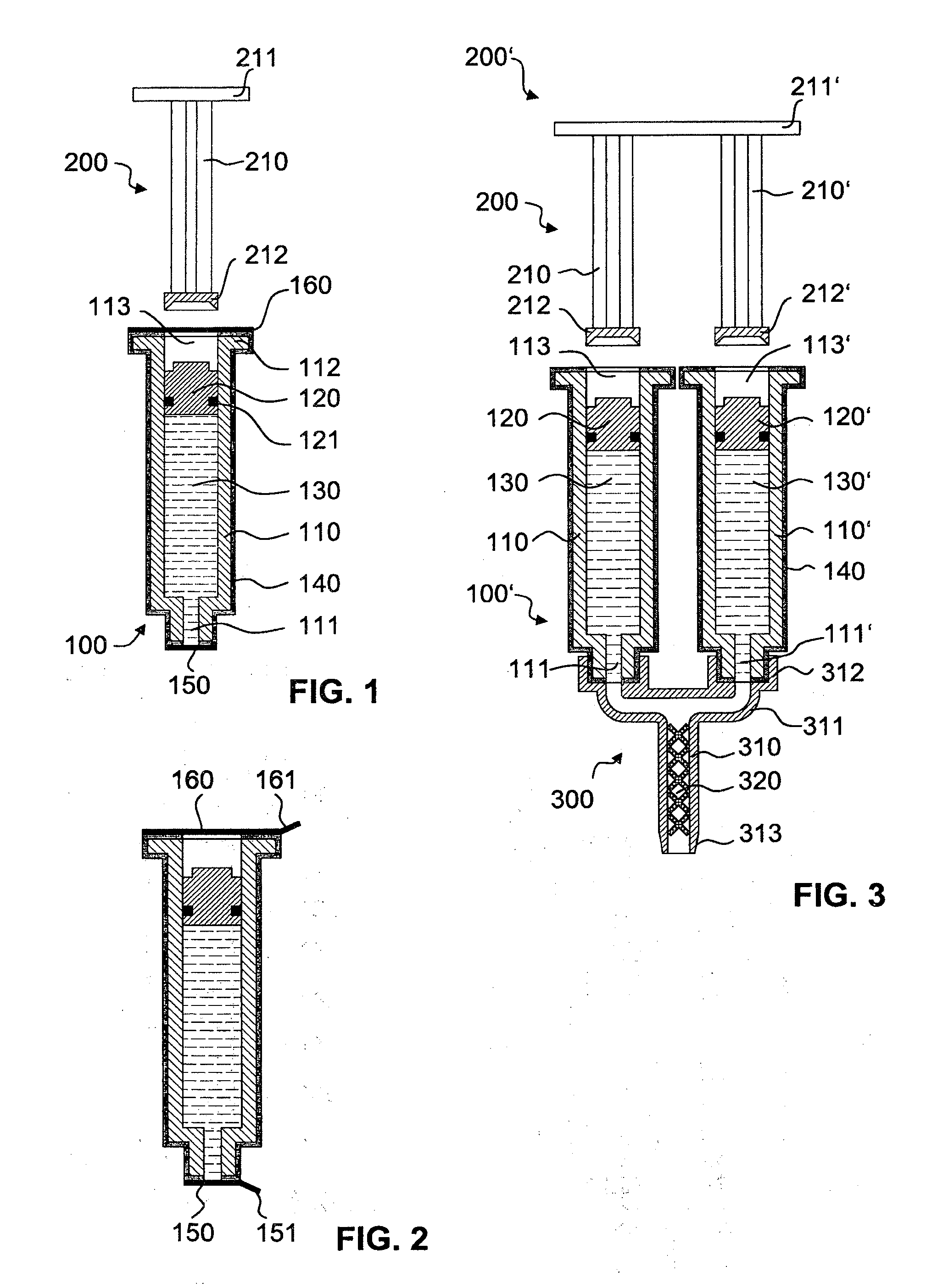
[0045]In FIG. 1, a container 100 is illustrated in highly schematic form. A hollow cylindrical main body (syringe body) 110 has an outlet opening 111 in a narrowed distal end area and has an actuation opening 113 at the opposite, proximal end. In the area of the actuation opening 113, a circumferential and radially outwardly projecting flange 112 is formed in order to permit a better hold of the syringe body 110 in the axial direction. This flange is flush, on the proximal face thereof, with that area of the syringe body surrounding the actuation opening 113. A piston 120 is arranged displaceably in the syringe body 110. The piston 120 is sealed by an O-ring 121 against the inner face of the wall of the syringe body 110. Another kind of seal is of course also possible. On its outer surface, the syringe body 110 has a coating in the form of a metallic barrier layer 140, which extends across the entire surface of the outside of the syringe body except for the openings 111, 113. The co...

second embodiment

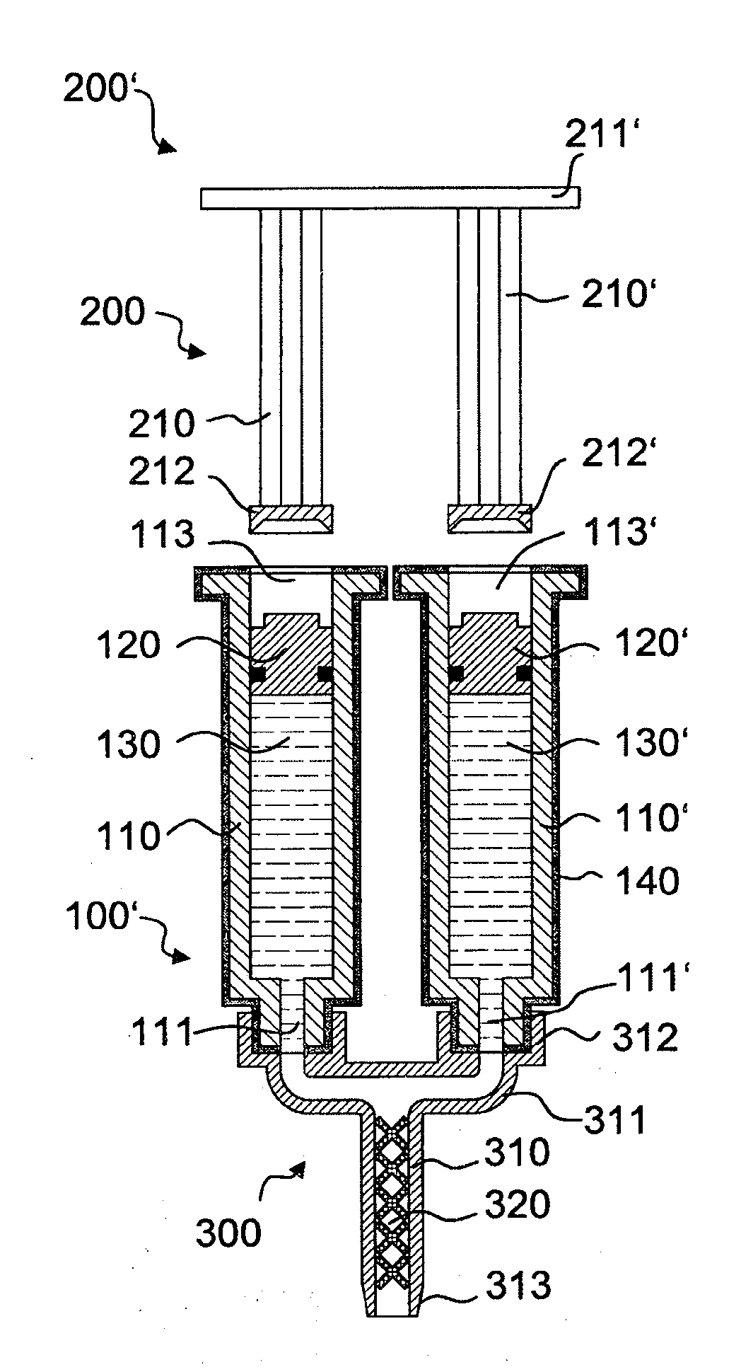
[0049]FIG. 3 is a highly schematic illustration of a second embodiment, in which the container 100′ is designed as a double syringe. Parts having the same function are designated by the same reference numbers as in FIG. 1. In addition to the first syringe body 110, a second syringe body 110′ arranged parallel to the latter is present, with a second outlet opening 111′ and a second actuation opening 113′. In this syringe body, a second piston body 120′ is arranged which, together with the syringe body, delimits a second product-receiving area for a second product 130′. The two syringe bodies 110, 110′ are rigidly connected to each other via a material bridge, not shown in FIG. 3. They are together provided with a coating 140.

[0050]In FIG. 3, the double syringe is shown after the seals have been removed. In the area of the outlet openings, a mixer 300 is connected in a securing area 312 to the container 100′. The mixer 300 has a mixing tube 310 with a static mixing element 320 and two...


PUM

PropertyMeasurementUnit
Fractionaaaaaaaaaa
Flow rateaaaaaaaaaa
Areaaaaaaaaaaa

Abstract

A syringe-type container comprising a hollow main body with a distal outlet opening and a proximal actuation opening for inserting an actuation element. A piston is displaceably arranged inside the main body for discharging a flowable product from the container. To reduce the permeability of the container, the main body has a diffusion-reducing layer. The outlet opening is closed with a first removable or severable seal, and the actuation opening is closed with a second seal.

Description

TECHNICAL FIELD[0001]The present invention relates to a container with a main body, in the interior of which a piston is displaceably arranged. Such containers are referred to hereinbelow as syringe-like containers.PRIOR ART[0002]Syringes and syringe-like containers are known for many uses in the medical and non-medical fields. Thus, a normal disposable injection syringe comprises a hollow cylindrical syringe body made of plastic, in which a piston is displaceably arranged. The piston is generally connected fixedly to a piston rod, which extends out of the syringe body in the proximal direction. An actuation flange is generally formed on the proximal end of the piston rod, and two mutually opposite holding flanges are generally formed on the syringe body. The syringe is held between index finger and middle finger or ring finger. The thumb is used to apply pressure to the actuation flange, such that a product located in the syringe is discharged through a distal outlet opening. The c...

Claims


Application Information

Patent Timeline
IPC IPC(8): B67D7/70B67B1/00G01F11/00B65B1/04
CPCA61M5/19A61M5/3129A61M2005/3121A61M2005/3118A61M2005/3117
Inventor GRETER, ANDYVUKIC, MATHEY
Owner MEDMIX SYST
Why Eureka
Try Eureka