
Control device and method for controlling a redundant connection in a flat network

a control device and flat network technology, applied in the direction of programme control, total factory control, instruments, etc., can solve the problems of increasing complexity, introducing unnecessary complexity and costs, and no further connection to improve redundancy can be added without increasing complexity

Active Publication Date: 2020-07-30
SCHNEIDER ELECTRIC IND SAS
View PDF7 Cites 3 Cited by
  • Summary
  • Abstract
  • Description
  • Claims
  • Application Information

AI Technical Summary

Benefits of technology

The invention is a device network consisting of at least two field devices, a primary control device and a primary switch, and a secondary control device and a secondary switch connected in a daisy chain loop topology. The secondary control device is able to logically enable or disable the Ethernet port of the secondary switch. The technical effect of this invention is improved network security and reliability.

Problems solved by technology

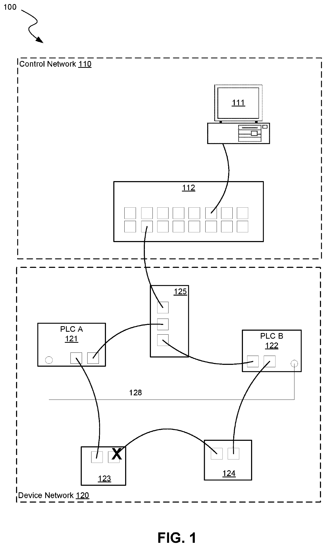
A drawback of the configuration 100 of FIG. 1 is that there is only one connection between the networks and that no further connection to improve redundancy can be added without increasing complexity to address the need for routing.
However, this introduces unwanted complexity and costs.

Method used


Image

  • Control device and method for controlling a redundant connection in a flat network
  • Control device and method for controlling a redundant connection in a flat network
  • Control device and method for controlling a redundant connection in a flat network

Examples


Embodiment Construction

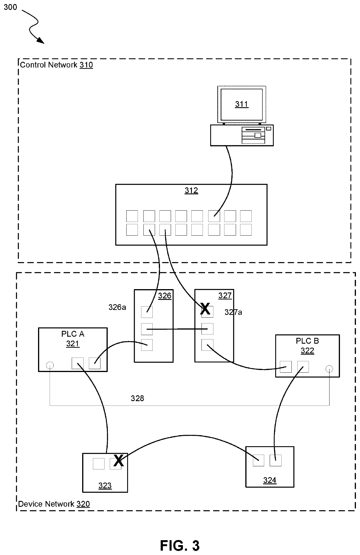
[0020]Referring to FIG. 3, an example of an IT-OT configuration 300 in accordance with the invention is shown. The IT-OT configuration 300 includes a control network 310 and a device network 320. The control network 310 includes a main computer system 311 and a Layer 2 switch 312. The device network includes two field devices 323, 324, a primary PLC 321 and a primary switch 326, and a secondary PLC 322 and a secondary switch 327. In this example the switches are shown as separate devices, in other examples they may be respectively integrated within the primary and secondary PLCs 321, 322. The primary PLC 321 and switch 326, secondary PLC 322 and switch 327, and field devices 323, 324 are connected in a daisy chain loop topology. Apart from the connections for the control network, the PLCs are also connected over a dedicated connection 328, such as a redundant point-to-point fibre optics based connection, a backplane bus, a proprietary Ethernet link, or fieldbus.

[0021]The secondary P...


PUM


Abstract

A control device having an integrated switch and being configured to logically enable and disable an Ethernet port of the integrated switch. Further disclosed is a device network consisting of at least two field devices, a primary control device and a primary switch, a secondary control device and a secondary switch, which are connected in a daisy chain loop topology. And wherein the secondary control device is configured to logically enable and disable an Ethernet port of the secondary switch. Further disclosed is a flat network consisting of such a device network. Further disclosed is a method for controlling a redundant connection in a flat network, consisting of detecting failure of the primary control device, initiating failover, enabling the Ethernet port of the secondary switch, and disabling the Ethernet port of the primary switch.

Description

[0001]The present invention relates to a method for controlling a redundant connection in a flat network and a system architecture enabling such control.BACKGROUND[0002]Industrial automation systems are provided to perform, control and supervise industrial processes. These automation systems are built from multiple devices, such as Programmable Logic Controllers (PLCs), Programmable Automation Controllers (PACs)), input / output devices (I / O devices), field devices (e.g., sensors and actuators), being interconnected via an Operational Technology OT-network i.e. industrial device network, using industrial protocols such as Modbus, ODVA EtherNet / IP, Profinet, etc. Such automation systems are also commonly connected to an enterprise Information Technology IT-network, i.e. control room network, which uses common IT protocols over TCP / IP and Ethernet IEEE 802.3 for exchange of data and signals with e.g. ERP-systems or other data management systems. These industrial automation systems and e...

Claims


Application Information

Patent Timeline
IPC IPC(8): H04L12/24H04L12/931G06F13/37H04L49/111
CPCH04L49/351H04L41/0816H04L41/0886G06F13/37H04L41/0668H04L49/10H04L49/30H04L49/557G05B19/41855G05B2219/14014G05B2219/24175Y02P90/02
Inventor ADRAGNA, JEAN-JACQUESBARBIER, KÉVINBRÜCK, ANTOINEEROJIRAO, ABHIJITHGARCIA MARTIN, FRANCISCOBUCHET, YANNICK
Owner SCHNEIDER ELECTRIC IND SAS
Learn More