
Automatic addressing method in an ethernet communication architecture

a communication architecture and automatic configuration technology, applied in the direction of electrical equipment, circuit arrangements, transmission, etc., can solve the problem of not allowing the client modules situated downstream to exchange with the server modul

Inactive Publication Date: 2017-03-09
SCHNEIDER ELECTRIC IND SAS
View PDF13 Cites 11 Cited by
  • Summary
  • Abstract
  • Description
  • Claims
  • Application Information

AI Technical Summary

Benefits of technology

The patent describes a way to connect multiple computer modules using Ethernet cables. By using one communication port of the switch in each module, the system can identify each module sequentially as they connect to the server. This means that the server can communicate with each module separately, and that the modules can communicate with each other without interference.

Problems solved by technology

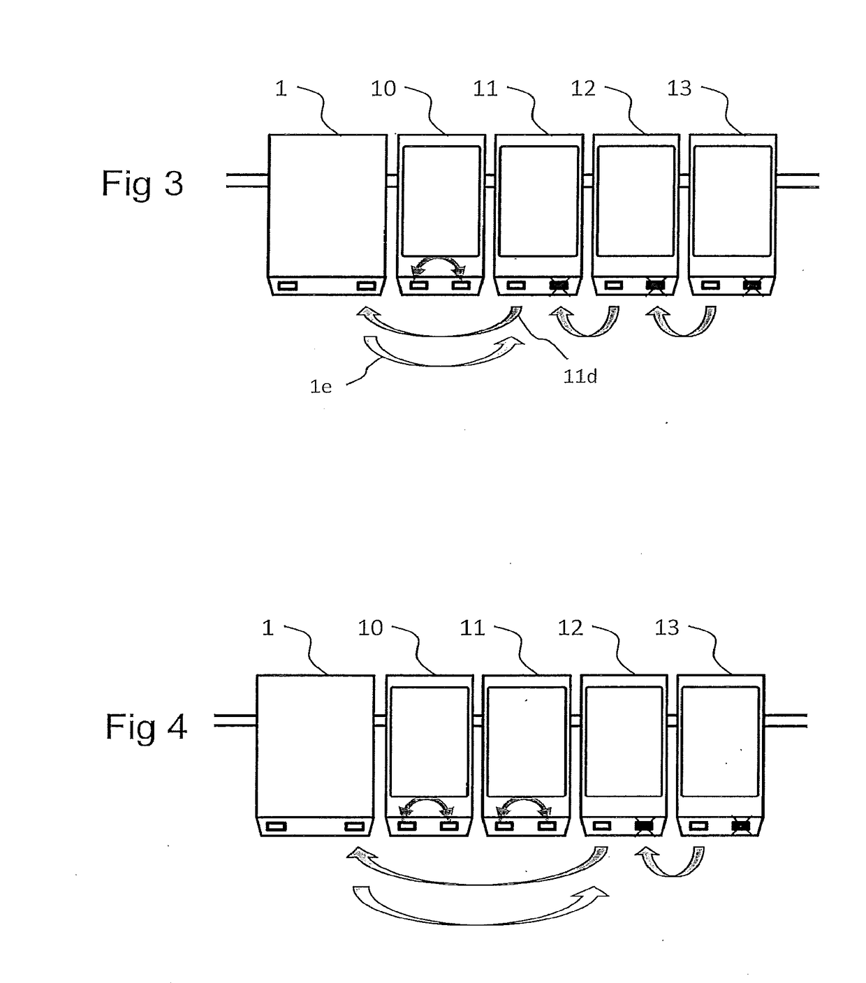
Indeed, as long as an identifier is not allocated to a client module, the latter does not activate its second communication port, thus not allowing the client modules situated downstream to exchange with the server module.

Method used


Image

  • Automatic addressing method in an ethernet communication architecture
  • Automatic addressing method in an ethernet communication architecture
  • Automatic addressing method in an ethernet communication architecture

Examples


Embodiment Construction

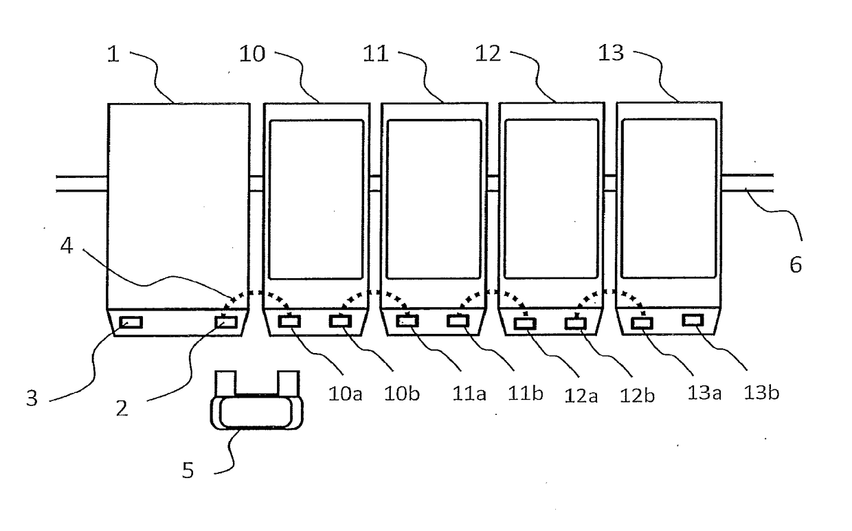
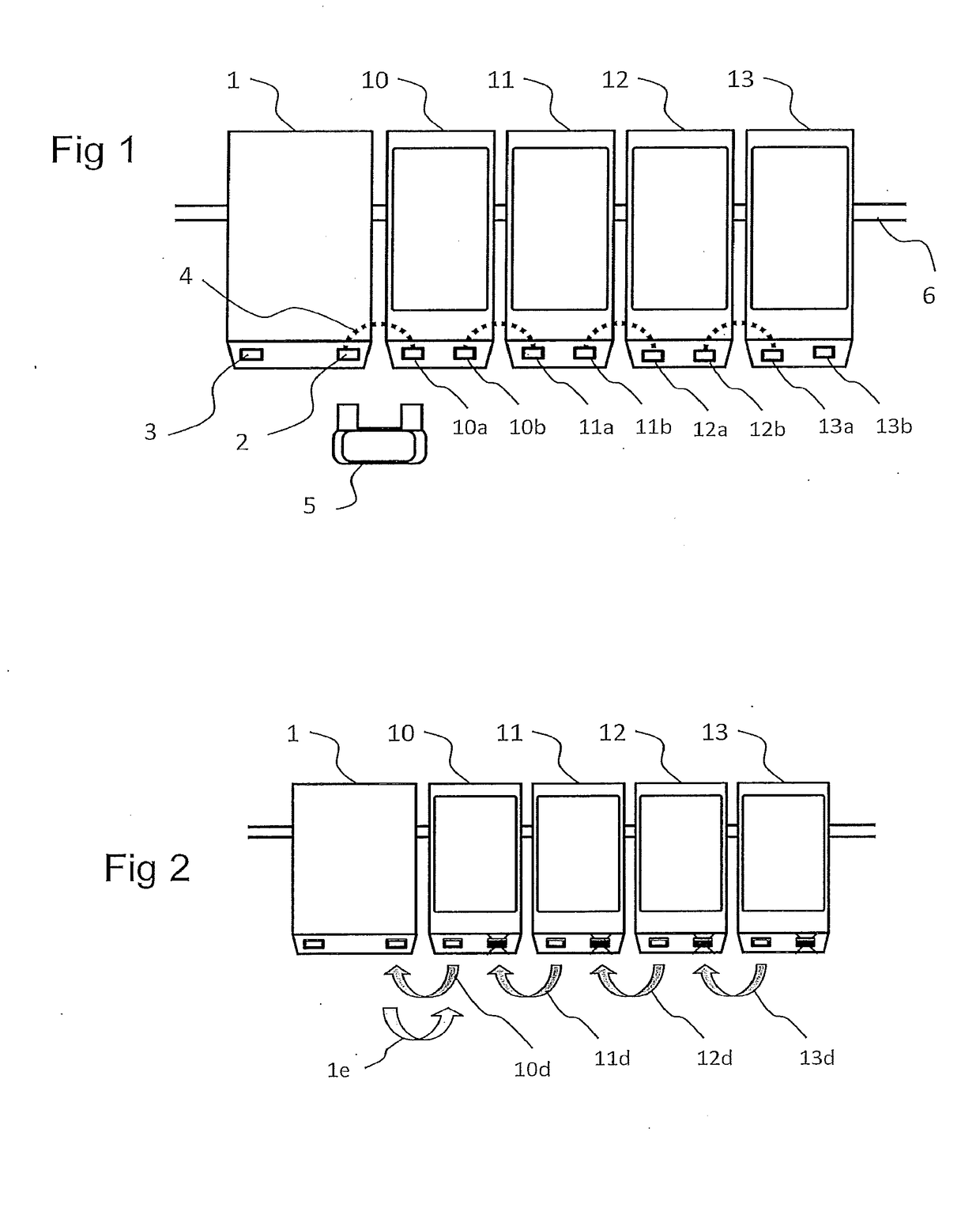
[0020]With reference to FIG. 1, a remote-control system comprises a server module 1 and a plurality of client modules. The various modules are connected together by an IP (Internet Protocol) Ethernet communication network with a physical connection of daisy-chain type 4, that is to say that the modules are connected in cascade (or in tandem). Each client module 10, 11, 12, 13 possesses an Ethernet switch which is furnished with two communication ports, called first port and second port hereinafter in the document. The first ports are called 10a, respectively 11a, 12a and 13a and the second ports are called 10b, respectively 11b, 12b and 13b. The Ethernet switch of a client module is capable of routing the messages between the first port and the second port and vice versa.

[0021]All the modules are linked together physically by a connection apparatus 5 which makes it possible to very easily connect and disconnect each module with its adjacent neighbour or neighbours (that is to say it...


PUM


Abstract

A method of configuration by a server module of several client modules connected together via an Ethernet communication network of daisy-chain type is provided. Each client module includes an Ethernet switch fitted with a first communication port and with a second communication port, in such a way that the first port of a first client module is connected to a communication port of the server module and that the first port of another client module is connected to the second port of an adjacent client module. The method includes for each client module an initialization step in which the client module activates its first port and deactivates its second port, an identification step in which the client module communicates with the server module via its first port for receiving an identifier, and an end-of-configuration step in which, once its identifier has been received, the client module activates its second port.

Description

TECHNICAL FIELD OF THE INVENTION[0001]The present invention pertains to a procedure for automatic configuration of addressing in a communication architecture comprising devices communicating with one another via an Ethernet communication network of daisy-chain type, that is to say that the devices are connected in cascade (or in tandem).[0002]A relevant field of application is for example the modular architecture of a remote-control station in an MV / LV sub-station of an electrical distribution network (MV: Medium Voltage, LV: Low Voltage). Such a remote-control station generally comprises various different functional modules that can ensure functions for measuring voltage / current at MV or LV equipment level, functions for monitoring quality and managing the electrical network, functions for fault detection, for command / control of equipment, etc.PRIOR ART[0003]This type of modular architecture (or modular RTU—Remote Terminal Unit) can also comprise a central server module in charge o...

Claims


Application Information

Patent Timeline
IPC IPC(8): H04L29/08H04L29/12
CPCH04L67/10H04L61/6022H04L61/6068H04L61/2015H04L61/5014H02J13/00028H02J13/00034H04L61/5038H04L2101/622
Inventor SINISTRO, STEPHANESUPTITZ, ERIC
Owner SCHNEIDER ELECTRIC IND SAS
Learn More