Width setting on a finishing train

a technology of finishing train and width setting, which is applied in the direction of metal rolling, metal rolling stands, metal rolling control devices, etc., can solve the problems of uneven widening of metal strips in finishing trains, inadequate methods, etc., and achieves the effect of simple and efficien

Active Publication Date: 2020-08-06
PRIMETALS TECH GERMANY
View PDF0 Cites 0 Cited by
  • Summary
  • Abstract
  • Description
  • Claims
  • Application Information

AI Technical Summary

Benefits of technology

[0020]The object of the present invention is to provide possibilities, by means of which the width of the metal strip can be set exactly in a simple and efficient manner.
[0031]Only a single width measurement and a single temperature measurement are thus required, specifically between the roughening train and the finishing train. Width deviations can be compensated for highly accurately. If a width regulation is additionally also to be implemented, an additional width measurement after the finishing train is required for this purpose. Such a width measurement is typically provided, however, and therefore does not require additional hardware expenditure.
[0032]In the simplest case, the actual widths and actual temperatures associated with the sections are identical to the detected actual widths and actual temperatures. However, preferably at least the detected actual widths, preferably also the detected actual temperatures are filtered, in particular low-pass filtered. By way of this procedure, the rolling of the metal strip can be performed relatively calmly (i.e., without high-frequency control interventions) in particular. The manipulation of the actual width via the strip tension thus has no negative effects on the rolling process.

Problems solved by technology

The methods often only function inadequately, however.
In addition, in a hot strip train without coil box, the temperature distribution is often uneven viewed over the length of the metal strip, which in turn results in an uneven widening of the metal strip in the finishing train.

Method used


Image

  • Width setting on a finishing train
  • Width setting on a finishing train
  • Width setting on a finishing train

Examples


Embodiment Construction

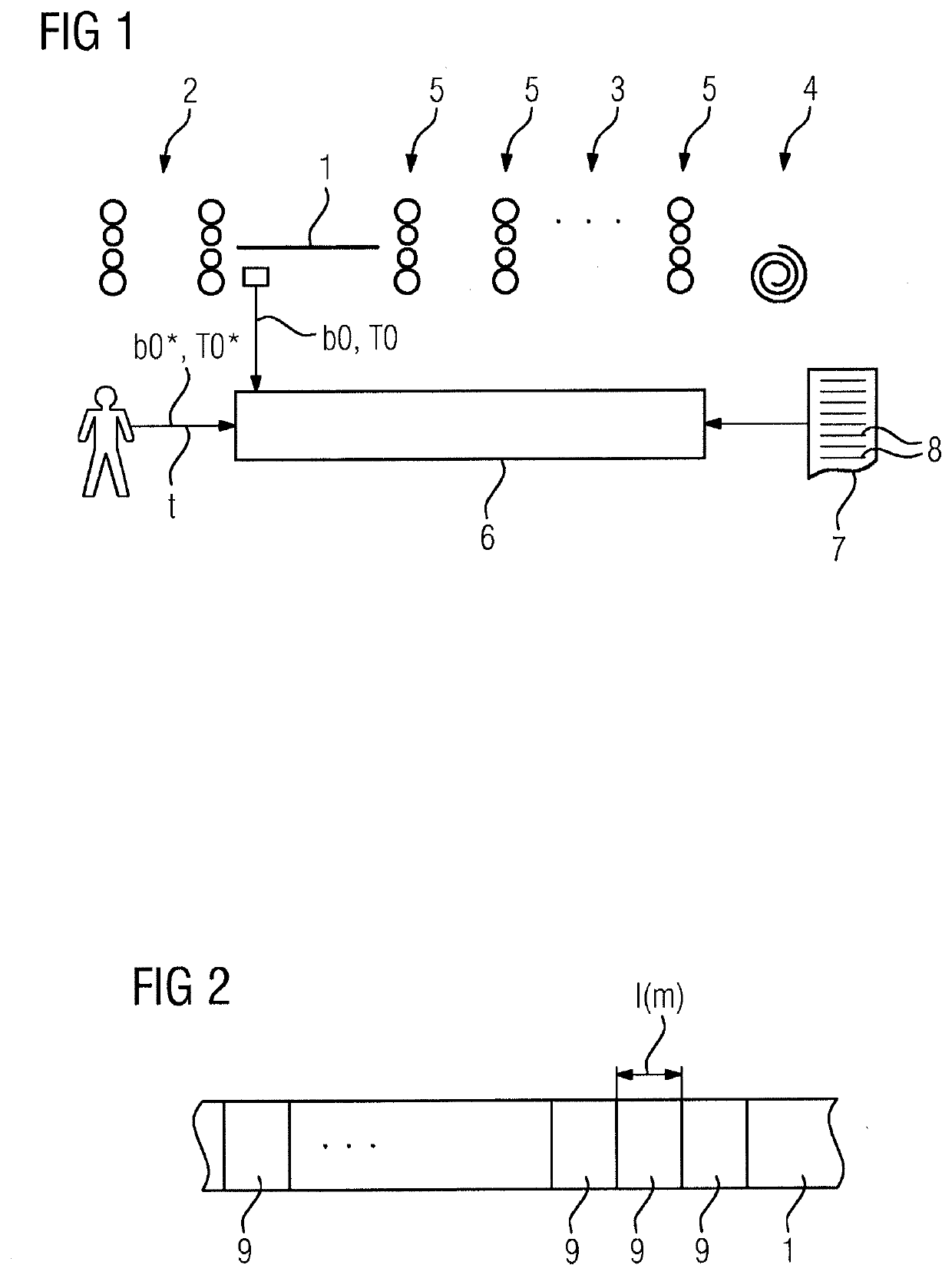
[0055]According to FIG. 1, a hot strip train for rolling a metal strip 1 has a roughening train 2, a finishing train 3, and a coiling device 4. The roughening train 2 can be omitted in individual cases—for example, in the case in which the metal strip 1 is already cast relatively thin. The finishing train 3 has, according to FIG. 1, multiple rolling stands 5, through which the metal strip 1 passes in succession. The number of rolling stands 5 is generally between three and eight, in particular between four and seven, for example, five or six. The metal strip 1 can be, for example, a steel strip, an aluminum strip, a copper strip, or a strip made of another metal.

[0056]The hot strip train—in particular the finishing train 3—is controlled by a control unit 6. The control unit 6 is programmed using a computer program 7. The computer program 7 comprises machine code 8, which is executable by the control unit 6. The execution of the machine code 8 by the control unit 6 causes the control...


PUM

PropertyMeasurementUnit
widthaaaaaaaaaa
widthaaaaaaaaaa
temperatureaaaaaaaaaa

Abstract

Before the rolling of a metal strip on a finishing train, the actual width and actual temperature of portions of the metal strip are respectively detected. The portions of the metal strip are tracked while they run through the finishing train. The rolling stands are respectively assigned width controlling devices which determine the setpoint width and the actual width after the rolling in the assigned rolling stand, and a downstream additional setpoint value, by which the desired tension downstream of the assigned rolling stand is corrected in order to bring the actual width closer to the setpoint width. The downstream additional setpoint value is both taken into account in the determination of the actual width and fed to a tension controller, which sets an actual tension, in the metal strip downstream of the assigned rolling stand, in accordance with the corrected setpoint tension. Determining the downstream additional setpoint value by the difference between the setpoint width and the actual width of a portion of the metal strip.

Description

CROSS-REFERENCE TO RELATED APPLICATIONS[0001]The present application is a divisional under 37 C.F.R. § 1.53(b) of prior U.S. patent application Ser. No. 15 / 511,693, filed Mar. 16, 2017, which is a 35 U.S.C. § 371 national phase conversion of PCT / EP2015 / 069501, filed Aug. 26, 2015, which claims priority of European Patent Application No. 14185055.2, filed Sep. 17, 2014. The entire content of each of these applications is incorporated in full by reference herein. The PCT International Application was published in the German language.TECHNICAL FIELD[0002]The present invention is directed to a method for rolling a metal strip in a finishing train, wherein the finishing train has multiple rolling stands, through which the metal strip passes in succession, and wherein the actual width and the actual temperature thereof is detected for each of the sections of the metal strip before they enter the finishing train.[0003]The present invention is furthermore directed to a computer program, whi...

Claims


Application Information

Patent Timeline
Patent Type & Authority Applications(United States)
IPC IPC(8): B21B37/22B21B38/04B21B38/00B21B37/50
CPCB21B37/48B21B2265/06B21B2261/06B21B2261/20B21B38/006B21B38/04B21B2273/20B21B37/22B21B37/50
Inventor KOTZIAN, DANIELTAUTZ, WILFRIED
Owner PRIMETALS TECH GERMANY
Why Eureka
Try Eureka