Method for manufacturing connecting members for connecting an aircraft wing to a center wing box, using preforms
Pending Publication Date: 2020-08-06
AIRBUS OPERATIONS SAS
View PDF1 Cites 1 Cited by
Summary
Abstract
Description
Claims
Application Information
AI Technical Summary
This helps you quickly interpret patents by identifying the three key elements:
Problems solved by technology
Method used
Benefits of technology
Benefits of technology
The patent proposes a method for making connecting members for aircraft that is quick and inexpensive. By using composite materials and assembling them, the method allows for the creation of strong and cost-effective connecting members that meet the requirements for transferring load between the wings, center wing box, and fuselage of the aircraft. These methods can help improve the manufacturing process for aircraft and make them more efficient.
Problems solved by technology
They are therefore expensive to manufacture and require a long manufacturing time.
Method used
Image
Click on the blue label to locate the original text in one second.
Reading with bidirectional positioning of images and text.
Examples
first embodiment
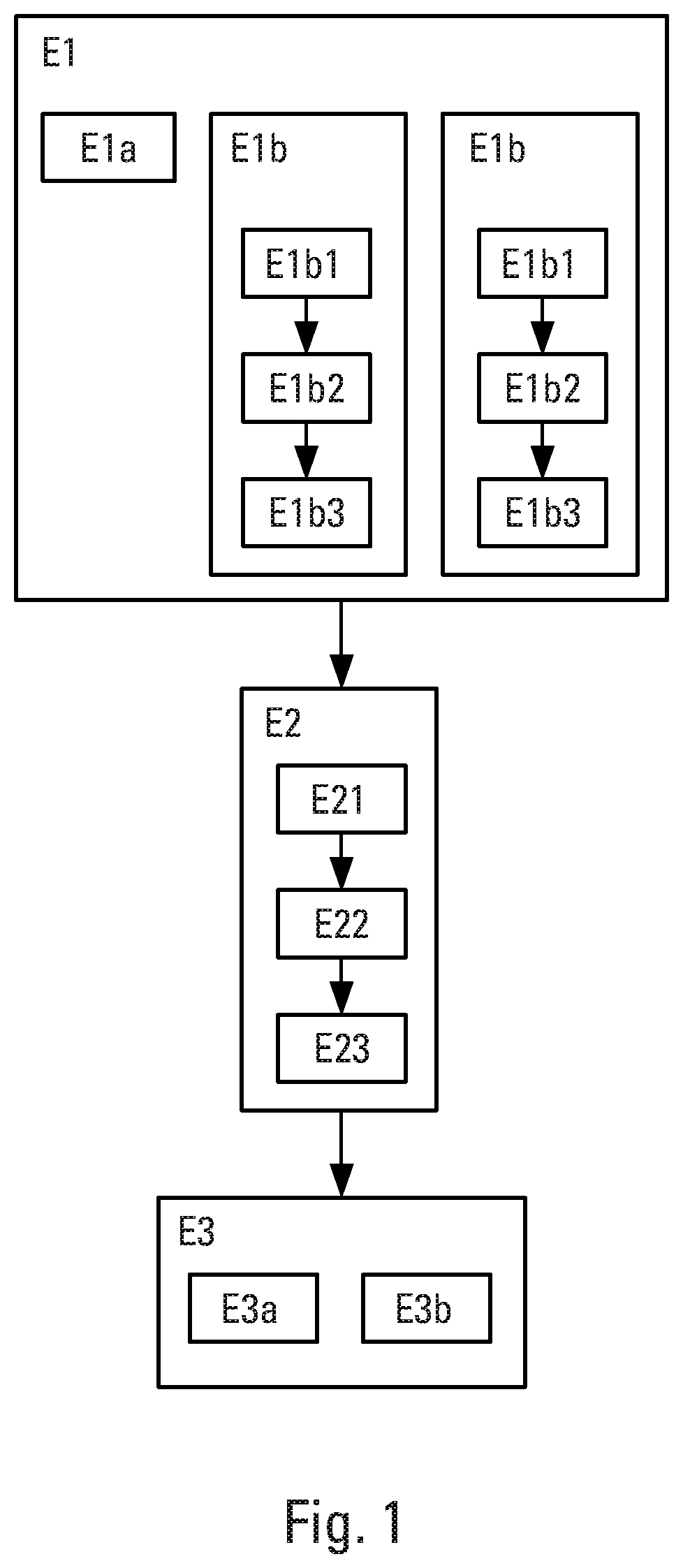
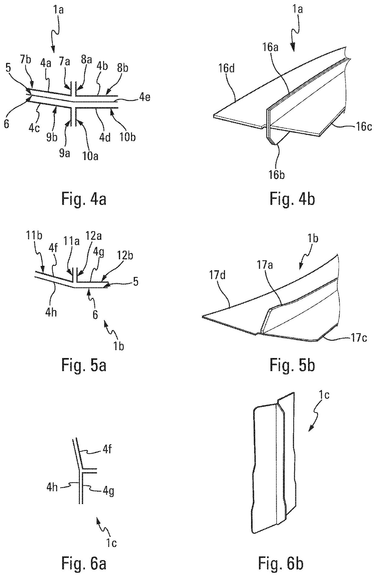
[0095]According to the method, the step E1 of manufacturing a cross-shaped connecting member 1a may comprise a manufacturing substep E1a that manufactures one main preform 4e and four manufacturing substeps E1b that manufacture respectively an L-shaped preform 4a, an L-shaped preform 4b, an L-shaped preform 4c and an L-shaped preform 4d.
[0096]The assembly step E2 may comprise a substep E21 of assembling the preforms 4a, 4b, 4c, 4d, 4e manufactured in the manufacturing substeps E1a, E1b.
[0097]The assembly step E2 may further comprise a stitching substep E22 which follows the preforms-assembly substep E21. The stitching substep E22 adds reinforcing fibers 21 by stitching to secure the preforms 4a, 4b, 4c, 4d, 4e to one another (FIG. 10).
[0098]The assembly step E2 may also comprise a heat treatment step E23 that heat treats the preforms 4a, 4b, 4c, 4d, 4e assembled in the assembly substep E21.
[0099]The preforms 4a, 4b, 4c, 4d, 4e are assembled, in the assembly substep E21, so that th...
second embodiment
[0108]According to the method, the step E1 of manufacturing a T-shaped connecting member 1b, 1c may comprise a manufacturing substep E1a that manufactures one main preform 4h and two manufacturing substeps E1b that manufacture respectively an L-shaped preform 4f and an L-shaped preform 4g.
[0109]The assembly step E2 may comprise a substep E21 of assembling the performs 46f, 4g, 4h, manufactured in the manufacturing substeps E1a, E1b.
[0110]The assembly step E2 may further comprise a stitching substep E22 which follows the preforms-assembly substep E21. The stitching substep E22 adds reinforcing fibers 21 by stitching to secure the preforms 4f, 4g, 4h to one another (FIG. 10).
[0111]The assembly step E2 may also comprise a heat treatment step E23 that heat treats the preforms 4f, 4g, 4h assembled in the assembly substep E21.
[0112]The preforms 4f, 4g, 4h are assembled, in the assembly substep E21, so that the connecting member 1b, 1c formed by the preforms 4f, 4g, 4h has a T-shaped tra...
PUM
Property
Measurement
Unit
Time
aaaaa
aaaaa
Time
aaaaa
aaaaa
Abstract
A method is disclosed for manufacturing connecting members for connecting an aircraft wing to a center wing box, using preforms. The method involves a step of manufacturing at least one preform made of composite material forming the connecting member, and a step of assembling the preform or preforms by heat treatment to form the connecting member. The manufacturing method makes it possible, simply and quickly, to manufacture a connecting member that contributes to the connection between a center wing box of an aircraft and a wing of the aircraft.
Description
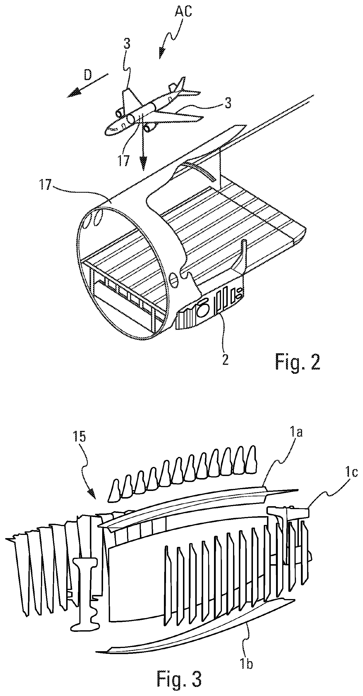
CROSS-REFERENCE TO PRIORITY APPLICATION[0001]This application claims the benefit of, and priority to, French patent application number 1901071, filed Feb. 4, 2019. The content of the referenced application is incorporated by reference herein.TECHNICAL FIELD[0002]The present disclosure relates to a method for manufacturing connecting members contributing to the connection between a center wing box of an aircraft and a wing of the aircraft. The disclosure also relates to a connecting member manufactured using said manufacturing method and to an aircraft comprising at least one such connecting member.BACKGROUND[0003]An aircraft comprises a fuselage and wings which are generally connected to the fuselage by means of a center wing box. The wings are fixed to the center wing box by a root joint comprising connecting members. The connecting members in general comprise profile sections the transverse cross sections of which are cross-shaped or T-shaped. The root joint has the main function ...
Claims
Application Information
Patent Timeline
Application Date:The date an application was filed.
Publication Date:The date a patent or application was officially published.
First Publication Date:The earliest publication date of a patent with the same application number.
Issue Date:Publication date of the patent grant document.
PCT Entry Date:The Entry date of PCT National Phase.
Estimated Expiry Date:The statutory expiry date of a patent right according to the Patent Law, and it is the longest term of protection that the patent right can achieve without the termination of the patent right due to other reasons(Term extension factor has been taken into account ).
Invalid Date:Actual expiry date is based on effective date or publication date of legal transaction data of invalid patent.

