Deployable satellite mast

a satellite mast and mast bearing technology, applied in the direction of cosmonautic components, cosmonautic parts, antennas, etc., can solve the problem of significant stresses at the mast bearing

Pending Publication Date: 2020-08-06
ARIANEGRP SAS
View PDF36 Cites 4 Cited by
  • Summary
  • Abstract
  • Description
  • Claims
  • Application Information

AI Technical Summary

Problems solved by technology

Solar panels of satellites have to provide a significant light colle

Method used


Image

  • Deployable satellite mast
  • Deployable satellite mast
  • Deployable satellite mast

Examples


Embodiment Construction

[0028]The present invention is concerned with structures which can be deployed on a satellite such as for example a structure which can in particular support solar panels and adapted to withstand stresses and strains created by these panels such as stresses and strains created by the thermal environment and motions of the satellite. It fulfils technical needs which are assisting in guiding the mast during its deployment and bringing stiffness to the mast after deployment.

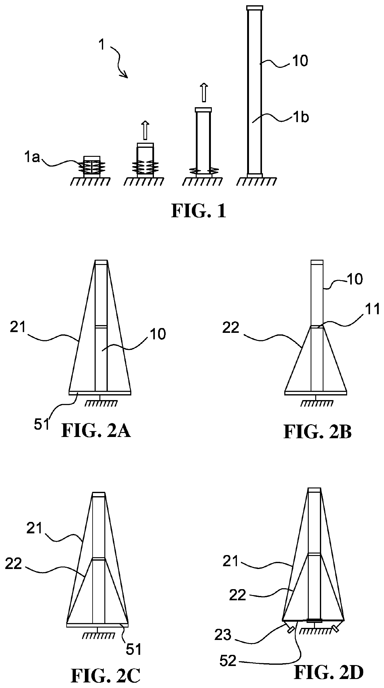
[0029]The invention relates to a deployable mast 1 such as depicted in FIG. 1 and mainly consisting of an inflatable tube 10, stored in an accordion shape 1a before deployment, and deployable by filling the tube by means of a gas according to a sequence such as represented, the deployed tube 1b forming a carrying structure.

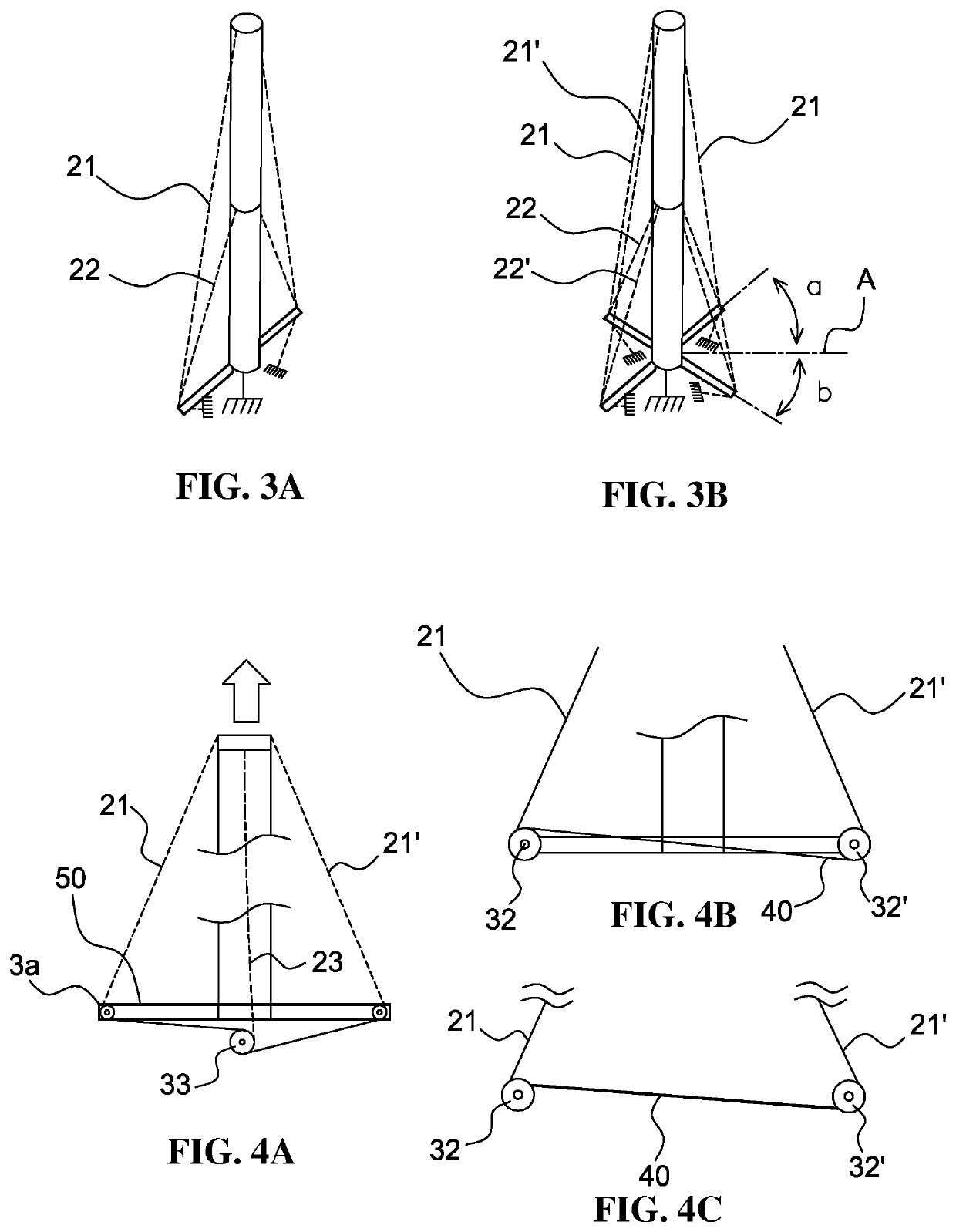
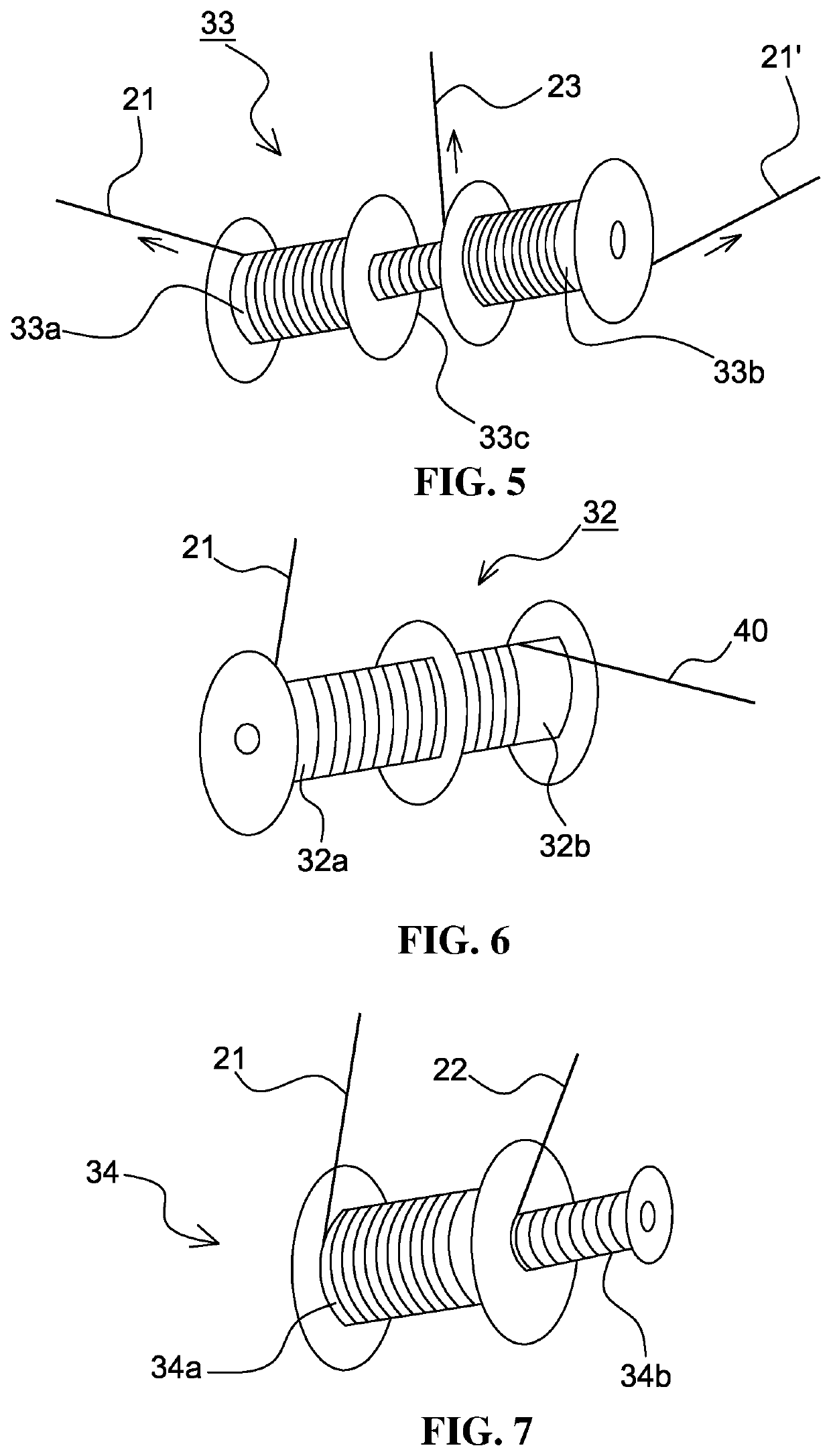
[0030]To assist in deploying the tube and rigidify it, the invention provides stays external to the tube as represented in FIGS. 2A to 2C.

[0031]Stays are flexible structures of the cable or wire t...


PUM


Abstract

A deployable satellite mast consisting of an inflatable tube, which is stored in fan-fold form before deployment and can be deployed by filling the tube with a gas, and which comprises a device for reinforcing and facilitating the deployment of the mast, which device is external to the mast and comprises one or more stays, first ends of which are wound on a reel device and second ends of which are secured to the tube, with the stays unwinding from the reel when the mast is deployed.

Description

FIELD OF THE INVENTION[0001]The present invention relates to structure supports for satellites of the inflation-deployable mast type.[0002]Technological Background[0003]A type of inflation-deployable masts is known in the space field. This mast is an accordion folded inflatable tube according to a tetragonal pattern before deployment and with a cylindrical shape after deployment. Such a mast supports a structure which is deployed when the satellite is in place and can be rigidified after inflation as described in document FR 2876983 A1.[0004]Its deployment can be further controlled by an inner structure as described in document FR 2877315 A1.[0005]Such masts can be made from metal films, from composites and are unfolded by means of the increase in pressure of a gas injected at the base thereof. Pressure pushes against the upper face of the tube and enables the mast to become longer until it achieves a cylindrical shape.[0006]They can be used in particular to carry structures such as...

Claims


Application Information

Patent Timeline
IPC IPC(8): B64G1/22B64G1/44
CPCH01Q1/288B64G2001/224H01Q1/081B64G1/44B64G1/222B64G1/22B64G1/62B64G1/2227
Inventor VILLEMAIN, ALEXIS
Owner ARIANEGRP SAS
Why Eureka
Try Eureka