Drill tap dilator

a dilator and drill tap technology, applied in the field of spinal surgery instruments, can solve the problems of affecting the operation, affecting the operation, and affecting the operation, and reducing the surgical steps. , to achieve the effect of reducing the surgical steps, minimizing the damage to the surgical site tissues, and reducing the impedance with the surrounding tissues

Active Publication Date: 2020-08-13
SPINEWAVE
View PDF0 Cites 7 Cited by
  • Summary
  • Abstract
  • Description
  • Claims
  • Application Information

AI Technical Summary

Benefits of technology

[0006]In accordance with one aspect, the subject drill tap dilator helps to aid in minimally invasive surgical options, particularly in cervicothoracic stabilization surgery. The drill tap instrument is particularly configured to reduce surgical steps, minimize damage to the surgical site tissues while inserting the dilator with a small profile to reduce impedance with the surrounding tissues. The drill tap dilator can be used with both lateral mass screw placement and cervical pedicle screw placement and may be used in both open and mini-open surgical techniques.
[0007]In another aspect, the subject drill tap dilator has teeth that are initially disposed in a retracted state. After using the front distal face of the dilator to press through tissue and dilate to the intended surgical site, the teeth can be extended with a control knob on the user end to dock into bone. Docking onto the bone around this intended surgical site often provides a solution, including the maintenance of the location of an already prepared surgical site and the reduction of the risk to the patient caused by drill and tap slippage.
[0008]In a further aspect, the subject dilator has an adjustable length with a stop face on the proximal back end of the instrument. Control of the adjustable length is achieved with the control knob on the user end of the instrument. This feature also minimizes or prevents over penetration of drills and taps.
[0009]Therefore, a dilator that combines dilation, bone docking, and depth stop adjustment keeps one instrument placed in position throughout the hole preparation procedure thereby reducing the chance of losing the surgical site and the potential of decreasing surgical time.

Problems solved by technology

Nevertheless, the ability to ensure proper placement of fixation devices, especially in less invasive procedures has been found to be more difficult using the posterior access approach.
For example, the starting of a pilot hole into the lateral mass and the subsequent tapping, drilling and introduction of a screw into the hole is tedious if the hole position is not maintained throughout the procedure.
A potential challenge for the McBride drill guide is that the pointed projections are always exposed, and as such, they may impede with surrounding tissue upon entrance into the surgical site.

Method used


Image

  • Drill tap dilator
  • Drill tap dilator
  • Drill tap dilator

Examples


Embodiment Construction

[0051]For the purposes of promoting an understanding of the principles of the invention, reference will now be made to the embodiments illustrated in the drawings and described in the following written specification. It is understood that no limitation to the scope of the invention is thereby intended. It is further understood that the present invention includes any alterations and modifications to the illustrated embodiments and includes further applications of the principles of the invention as would normally occur to one skilled in the art to which this invention pertains.

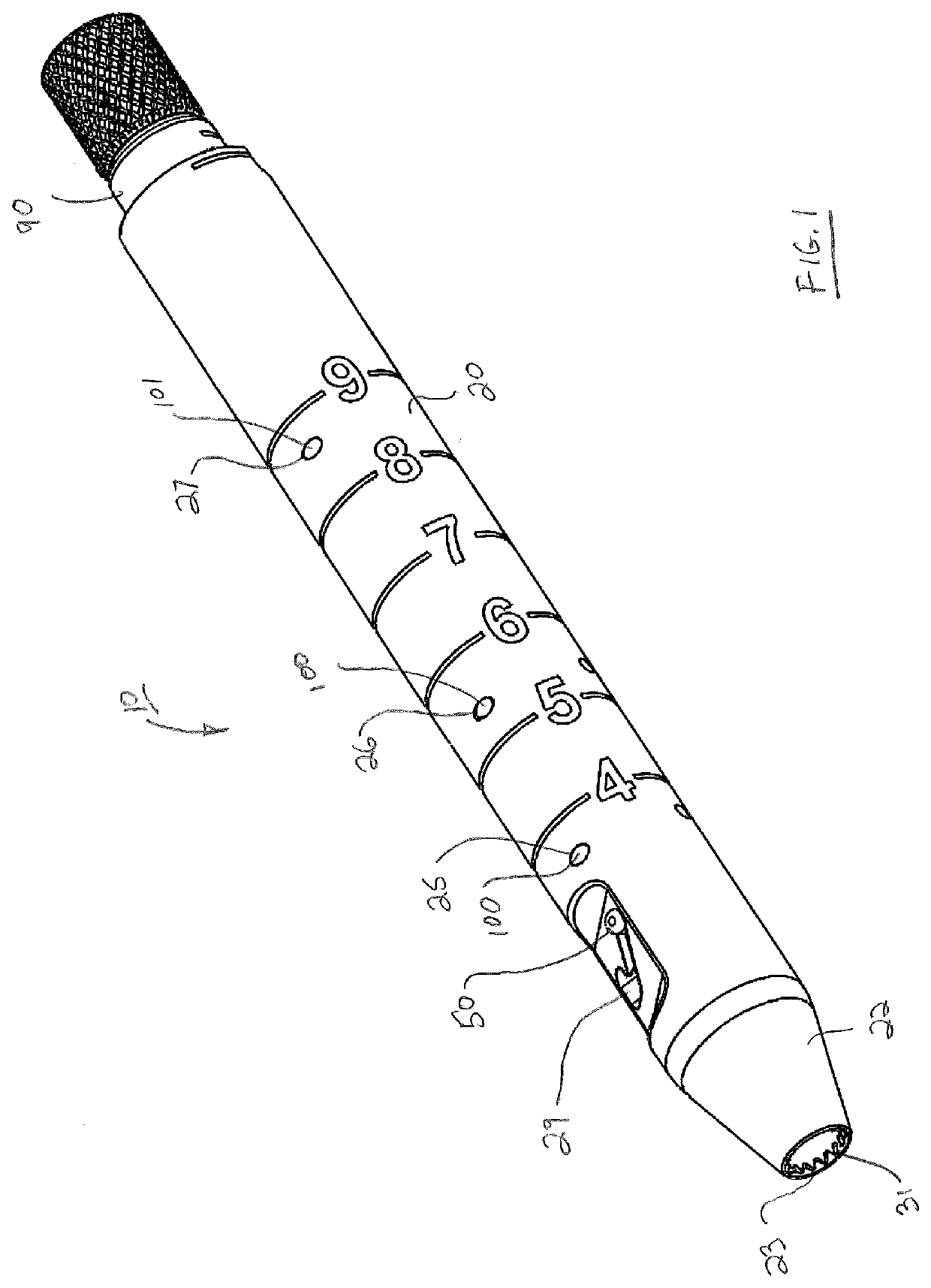
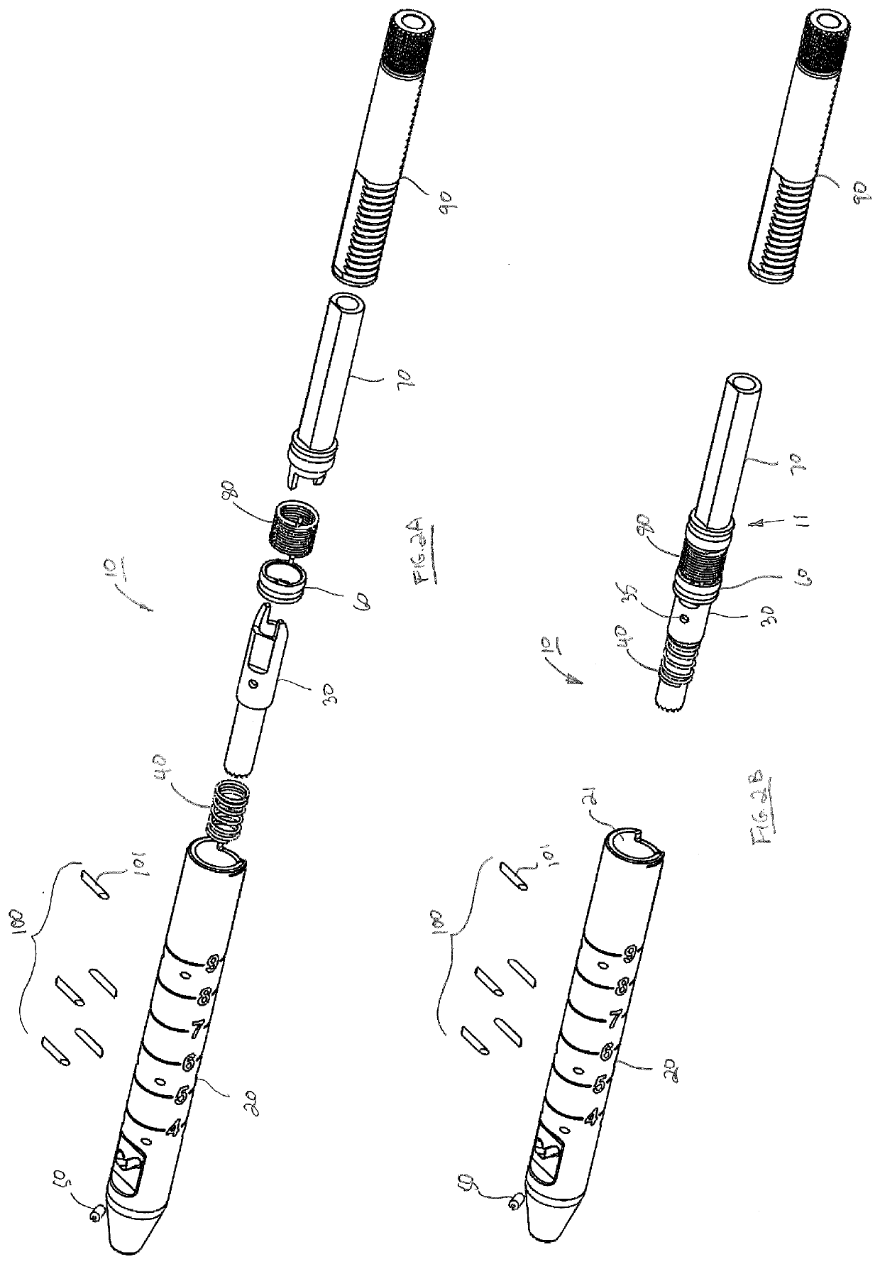
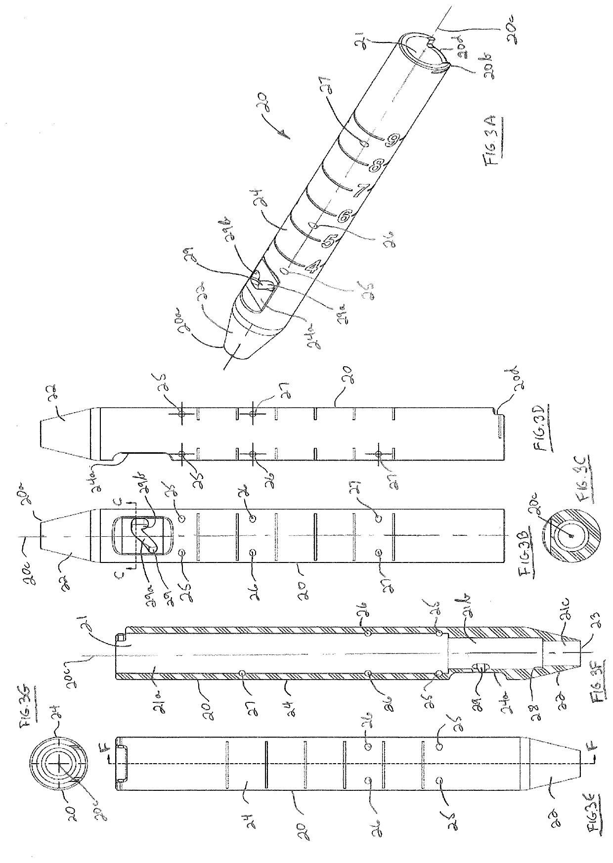
[0052]Turning now to FIG. 1 a drill tap dilator 10 in accordance with an exemplary embodiment is shown. Drill tap dilator 10 helps to aid in the minimally invasive placement of screws for spinal fixation particularly, but not exclusively, in cervicothoracic stabilization surgery. Drill tap dilator 10 may be used with both lateral mass screw placement and cervical pedicle screw placement in either open or mini-op...


PUM


Abstract

A drill tap dilator comprises a dilator body having a central lumen extending therethrough, an elongate sleeve slidably received with the lumen, and a control knob coupled to the sleeve. The control knob is movable rotatably and axially relative to the dilator body. The sleeve includes docking teeth that are extendable from a retracted position within the body lumen to a deployed position outside the body lumen upon rotation of the control knob relative to the dilator body in one rotational direction. Adjustment of the length of drill tap dilator is allowed upon rotation of the control knob in an opposite rotational direction relative to the dilator body and manual axial movement of the control knob relative to the dilator body.

Description

CROSS-REFERENCE TO RELATED APPLICATION[0001]This application claims the benefit of U.S. Provisional Patent Application No. 62 / 804,947, filed Feb. 13, 2019, the entire contents of which are incorporated by reference herein.FIELD OF THE INVENTION[0002]The subject invention relates to an instrument for use in spinal surgery, and more particularly to a dilator for use in facilitating screw placement in cervicothoracic stabilization surgery.BACKGROUND OF THE INVENTION[0003]In U.S. Patent Publication No. 2019 / 0342648 entitled “Lateral Mass Fixation Implant”, published Dec. 3, 2015, McCormack et al. describe a system and method for providing lateral mass fixation in the cervical spine using a posterior access. The inventors recognize that while anterior cervical spinal fusion is considered less traumatic, they believe that posterior cervical fusion with lateral mass screw or pedicle screw fixation provides a more rigid construct than anterior plates, interbody fusion or interspinous wiring...

Claims


Application Information

Patent Timeline
Patent Type & Authority Applications(United States)
IPC IPC(8): A61B17/16A61M29/00A61F2/44A61F2/46
CPCA61F2/446A61B17/1633A61F2/4611A61M29/00A61B17/1671A61B17/1757A61B17/1655A61B17/0218
Inventor GREGORY, ZACHARY
Owner SPINEWAVE
Why Eureka
Try Eureka