
System and a method for detecting wear of a ball-joint connection device of a rod, a rotor assembly, and an aircraft

Active Publication Date: 2020-08-13
EUROCOPTER
View PDF0 Cites 1 Cited by
  • Summary
  • Abstract
  • Description
  • Claims
  • Application Information

AI Technical Summary

Benefits of technology

The invention aims to create a system that can detect when a ball-joint connection device is worn out to the point where it needs to be removed. This will be useful for maintaining the performance and longevity of the device.

Problems solved by technology

Nevertheless, such terminology can appear inappropriate insofar as the ball sometimes includes at least one flat or even two flats at two diametrically opposite ends.
Nevertheless, the anti-fiction means, and / or the ball, and / or the outer cage naturally erode during the lifetime of the ball-joint connection device.
The resulting wear leads to unwanted clearance being created between the ball and the outer cage.
On an aircraft rotor pitch rod, such play has a harmful impact on the control of the aircraft.
Consequently, this wear ends up with the ball-joint connection device being replaced as a function of a removal criterion determined by the manufacturer.
Nevertheless, such clearance is difficult to measure and measurement may need to be performed following a procedure that can be lengthy and relatively expensive.
In addition to the relatively long duration of that procedure, an operator needs to make use of various tools in order to perform that maintenance action, which can make it more complicated to carry out.
Also, that procedure implies that the clearance is evaluated by a human being, which evaluation might therefore be erroneous.

Method used


Image

  • System and a method for detecting wear of a ball-joint connection device of a rod, a rotor assembly, and an aircraft
  • System and a method for detecting wear of a ball-joint connection device of a rod, a rotor assembly, and an aircraft
  • System and a method for detecting wear of a ball-joint connection device of a rod, a rotor assembly, and an aircraft

Examples


Embodiment Construction

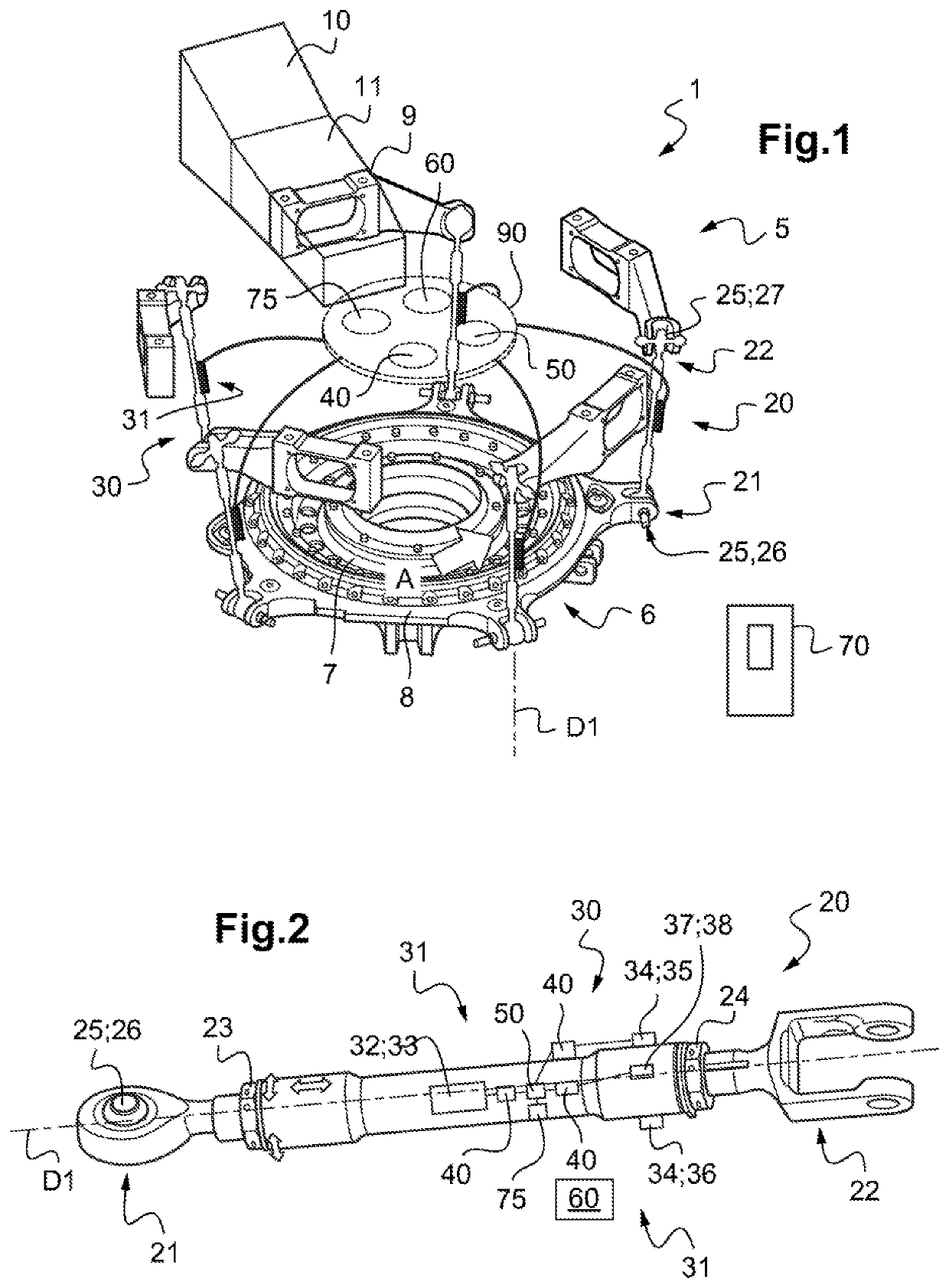
[0098]FIG. 1 shows an embodiment of a detection system 30 of the invention seeking to detect wear of a ball-joint connection device, referred to more simply as a “ball joint”.

[0099]By way of example, such a detection system 30 may be arranged on a rotor assembly 5, and in particular on a rotor assembly 5 of an aircraft 1, in order to detect wear of a ball-joint connection device 25 of a pitch rod 20.

[0100]Specifically, such a rotor assembly 5 may include a plurality of blades 10. Each blade 10 is carried by a rotor head not shown, possibly via a cuff 11 and / or via hinge and retaining devices. Certain blades may include cuffs that are integrated therein.

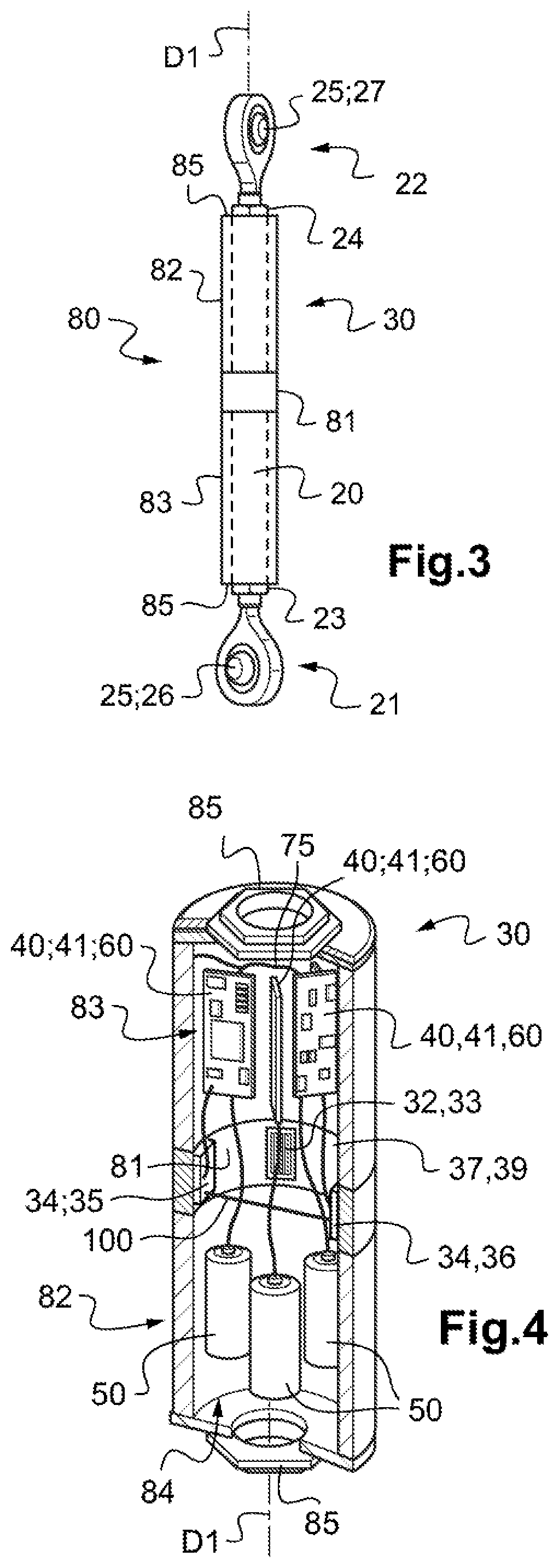
[0101]The rotor assembly 5 also includes multiple pitch rods, and in FIG. 1 it includes one pitch rod 20 for each blade 10 in order to connect each blade 10 to flight controls. Each pitch rod 20 extends longitudinally along its extension direction D1 from a first zone 21 to a second zone 22, the first zone 21 and / or the second zone 22...


PUM

PropertyMeasurementUnit
Timeaaaaaaaaaa
Frequencyaaaaaaaaaa
Energyaaaaaaaaaa

Abstract

The present invention relates to a detection system for detecting wear of a ball-joint connection device of a pitch rod. The detection system includes at least one measurement assembly, said at least one measurement assembly having at least one deformation gauge for placing on said pitch rod, said detection system comprising at least one electrical conditioning circuit connected to at least one said deformation gauge and to at least one electrical energy source, said electrical conditioning circuit being configured to generate a measurement signal that varies as a function of deformation of said at least one deformation gauge and as a function of said wear.

Description

CROSS REFERENCE TO RELATED APPLICATIONS[0001]This application claims the benefit of FR 19 01377 filed on Feb. 12, 2019, the disclosure of which is incorporated in its entirety by reference herein.FIELD OF THE INVENTION[0002]The present invention relates to a system and to a method for detecting wear of a ball-joint connection device of a connecting rod, to a rotor assembly, and to an aircraft provided with such system.BACKGROUND OF THE INVENTION[0003]In order to make a ball-joint connection between two mechanical parts, an operator can make use of a ball-joint connection device. Such a device is sometimes referred to more simply as a “ball-joint”.[0004]A ball-joint connection device may comprise an outer cage and a ball. The ball is then inserted in the outer cage in order to be rotatably movable relative to the outer cage. Anti-fiction means may be interposed between the spherical ball and the outer cage. The anti-fiction means may be fastened to the inner wall of the outer cage so...

Claims


Application Information

Patent Timeline
IPC IPC(8): F16C11/06B64F5/60B64C27/00
CPCF16C11/0647B64D2045/0085B64C27/006B64F5/60G01B21/32F16C7/02G01B7/18F16C2233/00F16C41/008F16C2322/59B64C27/54
Inventor DEPROUW, FLORENT
Owner EUROCOPTER
Features
  • Generate Ideas
  • Intellectual Property
  • Life Sciences
  • Materials
  • Tech Scout
  • Unparalleled Data Quality
  • Higher Quality Content
  • 60% Fewer Hallucinations
Learn More