HVAC system for a motor vehicle

a technology for motor vehicles and vacuum systems, applied in vehicle components, vehicle heating/cooling devices, transportation and packaging, etc., can solve the problems of not working, increasing the cost of such a flap assembly, and not being desirable, and achieve the effect of improving the controllability of the mixing temperatur

Active Publication Date: 2020-08-20
MAHLE INT GMBH
View PDF0 Cites 0 Cited by
  • Summary
  • Abstract
  • Description
  • Claims
  • Application Information

AI Technical Summary

Benefits of technology

[0008]It is therefore an object of the present invention to provide a HVAC system for a motor vehicle in which an improved controllability of the mixing tem...

Problems solved by technology

However, the problem arises in this regard that the throttling effect of one mixing flap or the two flaps used in the warm air path and in the cold air path does not change linearly with the rotation of the respe...

Method used


Image

  • HVAC system for a motor vehicle
  • HVAC system for a motor vehicle
  • HVAC system for a motor vehicle

Examples


Embodiment Construction

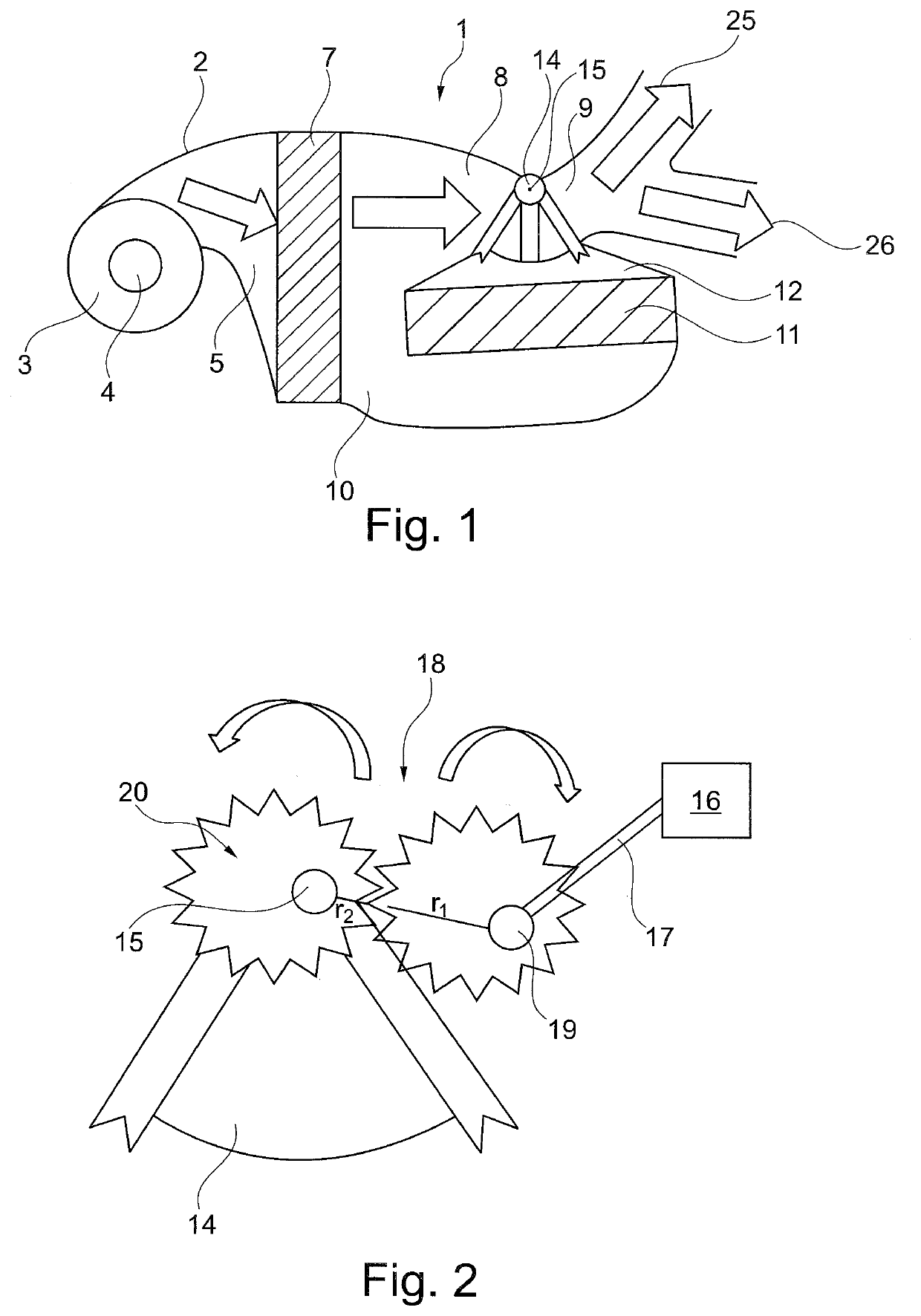
[0030]FIG. 1 shows a schematic representation of a HVAC system 1 for a motor vehicle, wherein the HVAC system has a housing 2. A blower 3 is provided in housing 2 for drawing in air through an air inlet 4. Air inlet 4 can be provided for admitting fresh air and / or circulating air. Depending on the design, a fresh air / circulating air flap can be provided for this purpose, which can be switched between fresh air or circulating air or a mixture thereof.

[0031]Furthermore, housing 2 has at least one air outlet or air exit 25 for discharging cold air, warm air, or mixed air. In the exemplary embodiment in FIG. 1, two air outlets or air exits 25, 26 are provided, through which temperature-controlled air can be discharged, for example, into a vehicle interior. More than two air outlets 25, 26 can also be provided, which can optionally also be controlled by at least one flap. Thus, for example, at least one footwell air outlet, at least one ventilation outlet, and / or at least one defrost out...


PUM


Abstract

A HVAC system for a motor vehicle having a housing, wherein the housing has an air inlet for admitting air and a cold air path in which cold air flows is provided in the housing and a warm air path in which warm air flows is provided in the housing, wherein the warm air path and the cold air path open into a mixing chamber, wherein a mixing flap is provided for controlling the proportion of cold air flowing into the mixing chamber and the proportion of warm air flowing into the mixing chamber, wherein the mixing flap is arranged rotatable about an axis and is driven by a flap actuator which has a drive shaft, wherein a gear with a nonlinear translation characteristic is provided between the mixing flap and the drive shaft.

Description

[0001]This nonprovisional application claims priority under 35 U.S.C. § 119(a) to German Patent Application No. 10 2019 202 301.0, which was filed in Germany on Feb. 20, 2019, and which is herein incorporated by reference.BACKGROUND OF THE INVENTIONField of the Invention[0002]The present invention relates to a HVAC system for a motor vehicle.Background of the Invention[0003]In HVAC systems for a motor vehicle, a cold air path and a warm air path are provided in a housing, wherein cold air by comparison flows through the cold air path and warm air by comparison flows through the warm air path. Air flows into the housing through an air inlet, wherein this air can be fresh air and / or circulating air. This air flows downstream of the air inlet through an evaporator and optionally also through a heating element. The air flowing through the evaporator is cooled and is accordingly cold air. The cold air accordingly flows in the cold air path starting from the evaporator. The air flowing th...

Claims


Application Information

Patent Timeline
IPC IPC(8): B60H1/00
CPCB60H2001/00721B60H2001/00135B60H2001/0015B60H2001/00078B60H1/00057B60H1/00664B60H1/00678B60H1/00857
Inventor LAUX, HOLGER
Owner MAHLE INT GMBH
Why Eureka
Try Eureka