
Fly-by-wire systems and related operating methods

a technology of flying by wires and operating methods, applied in the field of aircraft systems, can solve the problems of circuitry, or other costs, and increasing the amount of wiring and interfaces

Active Publication Date: 2020-08-20
HONEYWELL INT INC
View PDF0 Cites 10 Cited by
  • Summary
  • Abstract
  • Description
  • Claims
  • Application Information

AI Technical Summary

Benefits of technology

The patent text describes a vehicle electrical system for aircraft that includes a plurality of buses, control modules, and actuation control modules. The control modules are connected to specific subsets of the buses, while the actuation control modules are connected to different subsets of the buses. This arrangement allows for more efficient communication and control of the aircraft's flight control surfaces. The system also includes sensing arrangements that provide sensor data to the control modules, which in turn communicate with the actuation control modules to operate the aircraft's flight control surfaces. The technical effects of this system include improved efficiency and control of the aircraft's flight control surfaces.

Problems solved by technology

For safety purposes, fly-by-wire systems often employ redundancy to ensure they are fail operational; however, this often increases the amount of wiring and interfaces required.
Data integrity may further increase the amount of wiring, circuitry, or other costs.

Method used


Image

  • Fly-by-wire systems and related operating methods
  • Fly-by-wire systems and related operating methods
  • Fly-by-wire systems and related operating methods

Examples


Embodiment Construction

[0015]The following detailed description is merely exemplary in nature and is not intended to limit the subject matter of the application and uses thereof. Furthermore, there is no intention to be bound by any theory presented in the preceding background, brief summary, or the following detailed description.

[0016]Embodiments of the subject matter described herein relate to electrically-controlled vehicle systems. For purposes of explanation, the subject matter is described herein primarily in the context of aircraft where flight control surfaces are controlled using electrical signals, however, the subject matter is not necessarily limited to use with aircraft and may be implemented in an equivalent manner for other types vehicles (e.g., automotive vehicles, marine vessels, or the like).

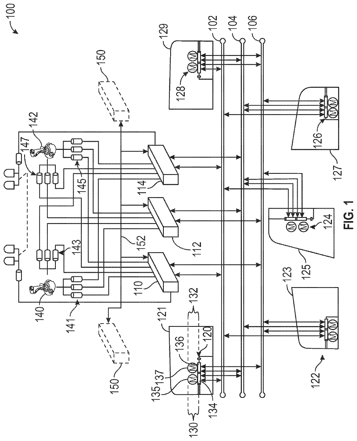
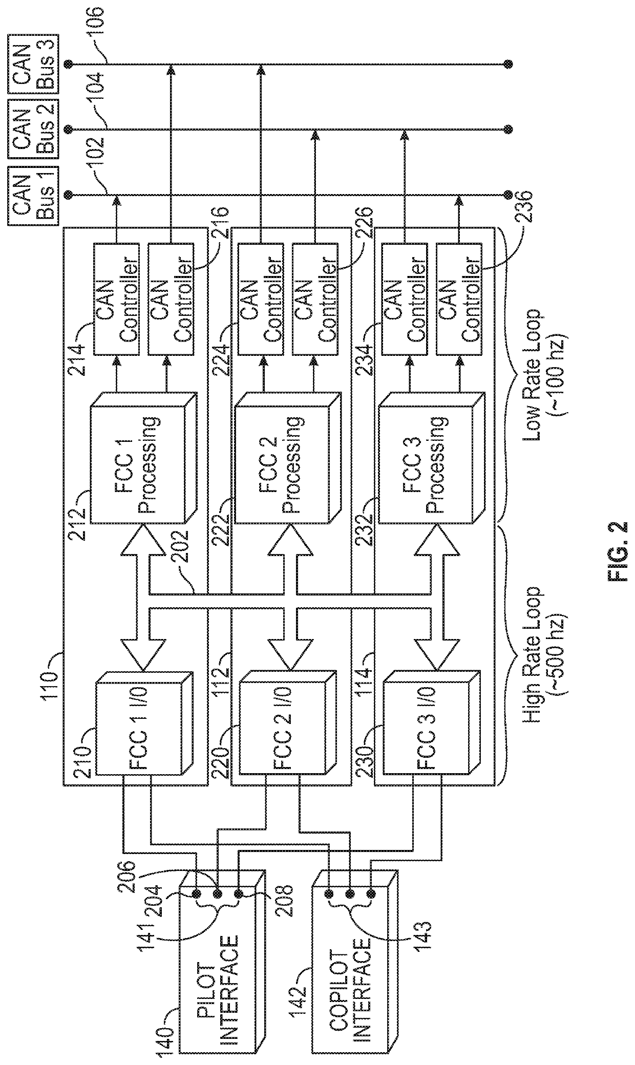
[0017]FIG. 1 depicts an exemplary embodiment of a fly-by-wire system 100 including a plurality of communications buses 102, 104, 106, a plurality of flight control modules 110, 112, 114, and a plural...


PUM


Abstract

Aircraft fly-by-wire systems and related vehicle electrical systems are provided. In one embodiment, an electrical system suitable for use with a control surface of a vehicle, such as an aircraft, is provided. The electrical system includes an asynchronous intermodule bus arrangement, a first vehicle control module, and a second vehicle control module. Each vehicle control module includes a respective interface arrangement to obtain and exchange data from different sensing arrangements with a first frequency, and a respective processing system to obtain the sensed data and determine actuator commands based on the sensed data with a lower frequency.

Description

TECHNICAL FIELD[0001]The subject matter described herein relates generally to aircraft systems, and more particularly, embodiments of the subject matter relate to redundant fly-by-wire systems.BACKGROUND[0002]In some modern aircraft, traditional mechanical flight control systems have been replaced with electrically controlled actuators, often referred to as fly-by-wire. Instead of mechanical linkages between cockpit controls and flight control surfaces, electrical signals are utilized to communicate movements of cockpit controls to actuators for the flight control surfaces. For safety purposes, fly-by-wire systems often employ redundancy to ensure they are fail operational; however, this often increases the amount of wiring and interfaces required. Data integrity may further increase the amount of wiring, circuitry, or other costs. Accordingly, it is desirable to provide a resilient fly-by-wire system that seeks to minimize the amount of wiring and associated costs. Other desirable ...

Claims


Application Information

Patent Timeline
IPC IPC(8): B64C13/50G05D1/00H04L12/40B64D43/00
CPCG05D1/0077H04L2012/40215H04L12/40B64D43/00B64C13/503H04L12/40006B64C13/50H04L2012/4028G06F13/4295G06F13/4004G06F13/405H04L12/40189
Inventor WILKENS, DEAN
Owner HONEYWELL INT INC
Learn More