Automatic analyzer

a technology of automatic analysis and analyzer, applied in the direction of material analysis, instruments, etc., can solve the problems of air suction, adverse influence on analysis, and inability to obtain accurate analysis results, so as to reduce user's work burden, improve user's operation efficiency, and prevent a reduction of throughput

Active Publication Date: 2020-08-20
HITACHI HIGH-TECH CORP +1
View PDF0 Cites 0 Cited by
  • Summary
  • Abstract
  • Description
  • Claims
  • Application Information

AI Technical Summary

Benefits of technology

[0017]Furthermore, according to the technique described in JP, A2014-145621, the ultrasonic generation mechanism and an installation space for the ultrasonic generation mechanism are required in addition to the liquid level imaging means, and a massive amount of data related to image analysis is required. As a result, cost increases and it is difficult to realize the automatic analyzer at low cost.
[0018]Moreover, the technique described in JP, A2004-125780 is proposed on the premise of a case in which it is determined that predetermined abnormal suction consecutively occurs, and describes cancelling analysis of the sample for remaining analysis items and going to the dispensing of a next specimen when the air suction continues a predetermined number of times or more. According to FIG. 17 of JP, A2004-125780, it is considered that when it is determined that the suction is the normal suction at one time before the number of times of consecutive air suction reaches the predetermined number of times, count of the predetermined number of times is then reset to zero and a sample is newly dispensed. In a case of such control, even if bubbles move on a surface of the specimen after it is determined that the suction is normal suction and the sample probe contacts the bubbles to result in air suction, the count of the number of times of consecutive air suction starts again from 1. When the air suction consecutively occurs, a suction operation is repeated until the number of times of consecutive air suction reaches the predetermined number of times. In this way, for a sample for which air suction occurs discontinuously, it is better to return the specimen to the user from the analyzer earlier once and eliminate the bubbles manually. However, the suction operation is repeated until the number of times of consecutive air suction reaches the predetermined number of times whenever the air suction occurs. This possibly delays the return of the specimen to the user.
[0019]Therefore, it is an object of the present invention to realize an automatic analyzer required to accurately dispense a liquid such as a sample or a reagent in a predetermined amount, in which attention is paid to the fact that even if bubbles are detected at the surface of the liquid are then often eliminated in short time or move, an operation of the suction of the liquid is re-executed when a cumulative number of times of air suction abnormality is smaller than a predetermined allowable cumulative number, whereby it is possible to reduce user's work burden without entailing cost increase. It is another object of the present invention to realize the automatic analyzer that cancels a request planned to the liquid for measurement items, starts the operation of the suction at another liquid planned next, and returns the liquid for which the request is cancelled for the measurement items to a user as early as possible when the cumulative number of times of air suction abnormality reaches the predetermined allowable cumulative number although air suction abnormality does not occur consecutively, whereby it is possible to ensure that the user take measures quickly.
[0023]The present invention can realize the automatic analyzer that can improve user's operation efficiency and reduce user's work burden while preventing a reduction of throughput without entailing cost increase by re-executing the operation of the suction of the specimen when the cumulative number of times of air suction abnormality is smaller than the predetermined allowable cumulative number even with the bubbles detected at the surface. In addition, the present invention can realize the automatic analyzer that can ensure that the user take measures quickly by returning the liquid to the user as early as possible when the cumulative number of times of air suction abnormality reaches the allowable cumulative number although air suction abnormality does not occur consecutively.

Problems solved by technology

For these procedures, if solutions such as the reagent and the specimen are not accurately dispensed in predetermined amounts, an accurate analysis result is unlikely to be obtained.
However, in this case, if bubbles are present on a surface of the solutiat the surface detection mechanism often, falsely detects a surface of the bubbles as the liquid level.
The suction of the solution then starts from a position that is not the position of the actual liquid level, which possibly results in the occurrence of air suction, a variation of a dispensing amount, and an adverse influence on an analysis result.
Nevertheless, bubbles are often generated when the user is unable to sufficiently check samples with eyes in a facility where many samples are handled or when the user sufficiently checks samples with eyes and then the samples completed with the check are subjected to secondary dispensing using an automatic preprocessing system.

Method used


Image

  • Automatic analyzer
  • Automatic analyzer
  • Automatic analyzer

Examples


embodiments

First Embodiment

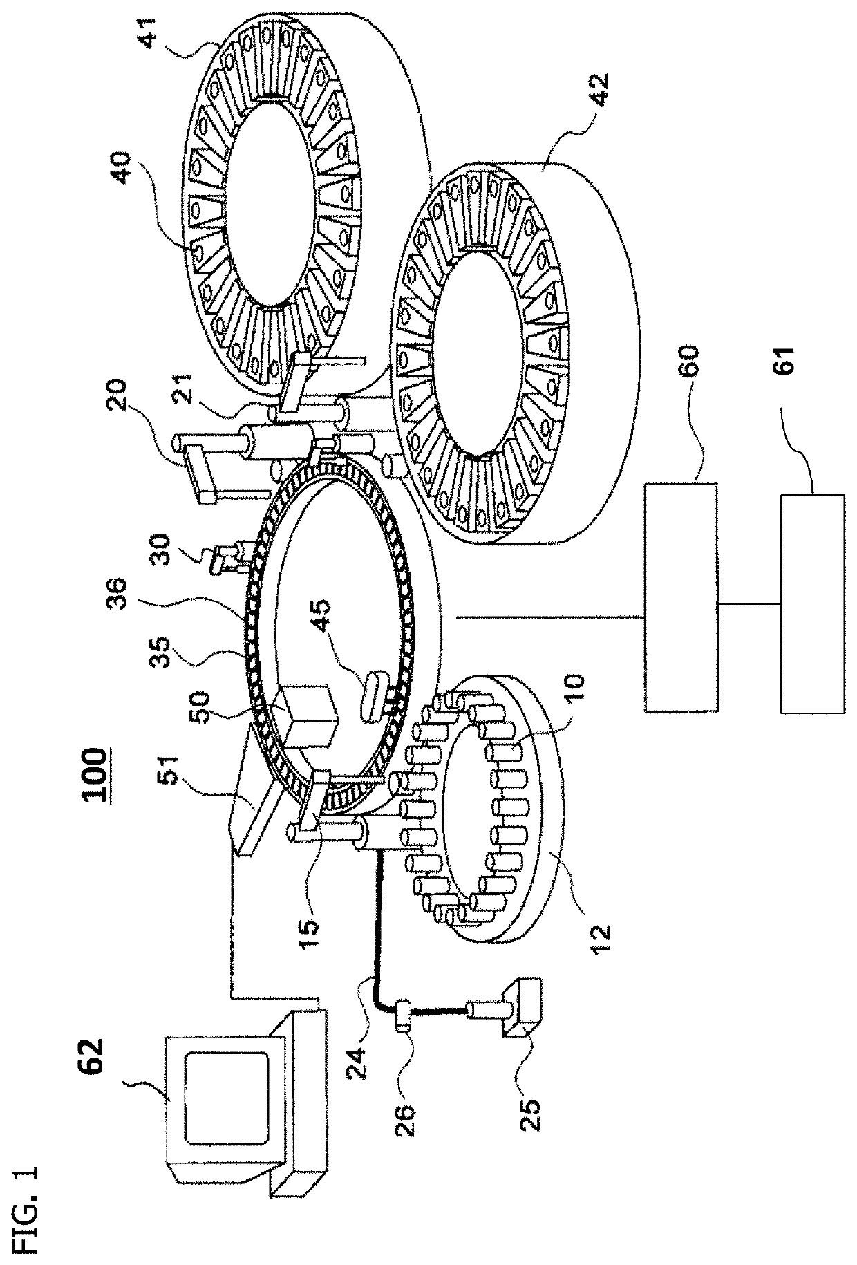
[0039]An example of an automatic analyzer to which a first embodiment of the present invention is applied will be described first while FIG. 1 is taken by way of example.

[0040]FIG. 1 is a schematic configuration diagram of an automatic analyzer 100 to which the first embodiment of the present invention is applied. In FIG. 1, the automatic analyzer 100 includes a sample disk 12, a first reagent disk 41, a second reagent disk 42, and a reaction disk 36. The sample disk 12 can mount sample containers 10 each holding a sample. The first reagent disk 41 and the second reagent disk 42 can mount reagent containers 40 each containing a reagent. Reaction containers 35 are disposed on a circumference of the reaction disk 36.

[0041]The automatic analyzer 100 further includes a sample dispensing mechanism 15, a first reagent dispensing mechanism 20, a second reagent dispensing mechanism 21, a stirring device 30, a container washing mechanism 45, a light source 50, a spectral sens...

second embodiment

[0127]A second embodiment of the present invention will next be described.

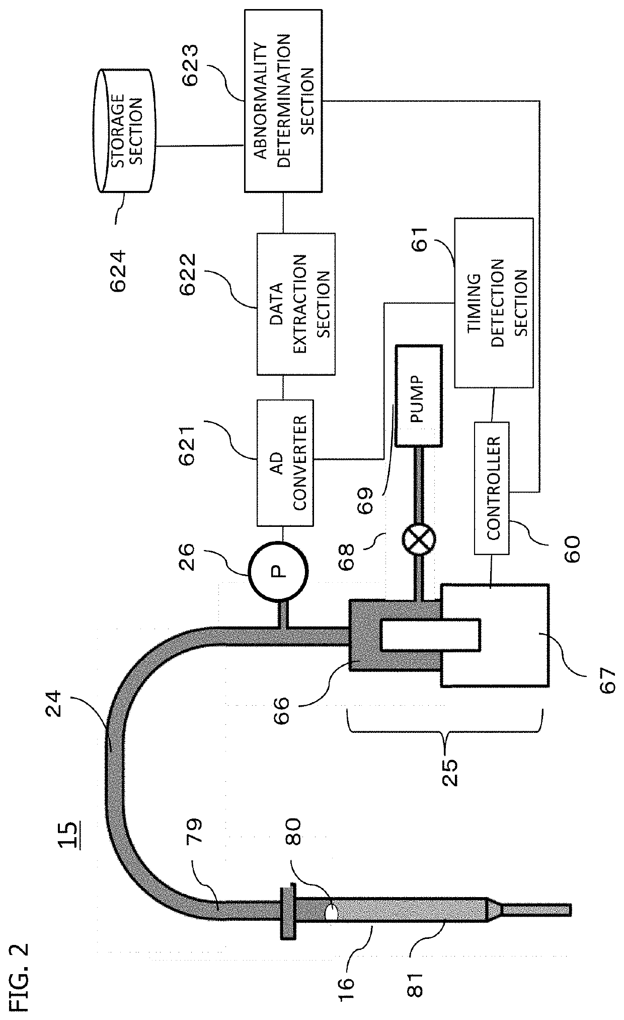
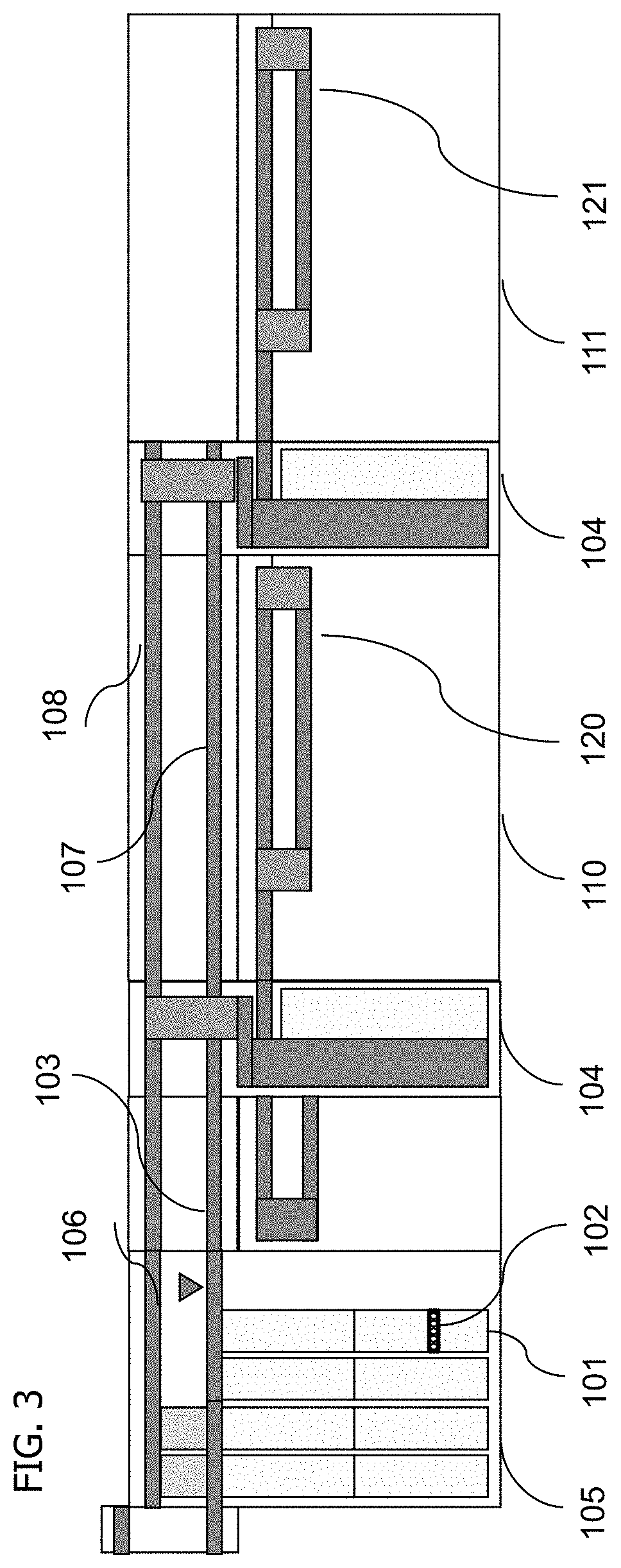
[0128]The second embodiment of the present invention is an example in which a system (combined system) includes the first unit 110 and the second unit 111 that are the analysis section of the automatic analysis system shown in FIG. 3, and in which the first unit 110 and the second unit 111 each use the same bubble detection method (bubble detection method by the change of the internal pressure of the sample probe 16 using the pressure sensor 26 similar to that according to the first embodiment). In other words, the first and second units 110 and 111 each determine that bubbles are present at the surface of the liquid on the basis of the change of the internal pressure of the probe after the probe contacts the bubbles. The dispensing mechanism for each probe is provided with the liquid level detection mechanism. For example, the first and second units 110 and 111 are both biochemical analysis units, or one of t...

third embodiment

[0148]A third embodiment of the present invention will next be described.

[0149]The third embodiment of the present invention is an example in which a system (combined system) includes the first unit 110 and the second unit 111 that are the analysis section of the automatic analysis system shown in FIG. 3, and in which the first unit 110 and the second unit 111 use different bubble detection methods (the bubble detection method by the change of the internal pressure of the sample probe 16 using the pressure sensor 26 similar to that according to the first embodiment and the bubble detection method by picking up an image of the liquid level by an imaging section). In other words, the second unit 111 determines that bubbles are present at the surface of the liquid in a non-contact manner. For example, one of the first and second units 110 and 111 is a biochemical analysis unit and the other is an immunoanalysis unit.

[0150]It is noted that the third embodiment will be described in the c...


PUM

PropertyMeasurementUnit
pressureaaaaaaaaaa
air suctionaaaaaaaaaa
pressure sensoraaaaaaaaaa

Abstract

The automatic analyzer includes: a liquid dispensing mechanism that performs suction of a liquid; a pressure sensor that measures a change of an internal pressure of a probe provided at the liquid dispensing mechanism; a determination section that determines whether the suction of the liquid by the probe is normal suction or air suction abnormality; an analysis section; a storage section that stores a cumulative number of times of air suction abnormality per liquid and an allowable cumulative number for the cumulative number of times of air suction abnormality; and a controller that exercises operation control over the liquid dispensing mechanism, the determination section, and the analysis section. The controller exercises control such that the cumulative number of times of air suction abnormality is updated and the updated cumulative number is stored in the storage section even if the air suction abnormality occurs non-consecutively.

Description

TECHNICAL FIELD[0001]The present invention relates to an automatic analyzer that includes a dispensing mechanism performing the suction of a solution such as a reagent or a specimen in a predetermined amount and delivering the solution to a reaction container.BACKGROUND ART[0002]An automatic analyzer for clinical laboratory tests measures a specific component in a biological sample such as a blood sample or a urine sample. General procedures of the automatic analyzer include dispensing a sample (specimen) from a sample container into a reaction container using a dedicated nozzle, and then dispensing a reagent from a reagent container into the reaction container that already contains the specimen using a dedicated nozzle. The general procedures further include, after stirring the sample and the reagent, inducing a reaction for fixed time, and making measurements by detection means in response to an absorbance and an amount of luminescence obtained from a reaction liquid.[0003]For the...

Claims


Application Information

Patent Timeline
Patent Type & Authority Applications(United States)
IPC IPC(8): G01N35/10G01N35/00
CPCG01N35/1016G01N35/00603G01N35/1002G01N2035/1018
Inventor SARWAR, SAYAKANISHIDA, MASAHARUINOUE, YOKOSHIMADA, MASAFUMIYAGI, KENICHIFUKAYA, NAOHIKOMCCAUGHEY, ANDREW
Owner HITACHI HIGH-TECH CORP
Why Eureka
Try Eureka