Microscopy method for determining a contrast image and microscope

Active Publication Date: 2020-08-20
CARL ZEISS MICROSCOPY GMBH
View PDF3 Cites 0 Cited by
  • Summary
  • Abstract
  • Description
  • Claims
  • Application Information

AI Technical Summary

Benefits of technology

[0045]The microscopy method according to the invention makes possible a simplified visualization of low-contrast objects in microscopy, for example in addition to imaging by means of a fluorescence method. For example, in transmitted light the object, for example cells or tissue sections, is imaged in its entirety, and also its state analyzed, since, because of the specificity of the stainability of for example certain proteins or protein complexes, the actual fluorescence microscopy does not provide any information on this

Problems solved by technology

Moreover, a number of optical elements have to be introduced both into the illuminating beam path and the imaging beam path, maki

Method used


Image

  • Microscopy method for determining a contrast image and microscope
  • Microscopy method for determining a contrast image and microscope
  • Microscopy method for determining a contrast image and microscope

Examples


Example

DETAILED DESCRIPTION OF THE DRAWINGS

[0063]In the figures, the same elements are provided with the same reference numerals.

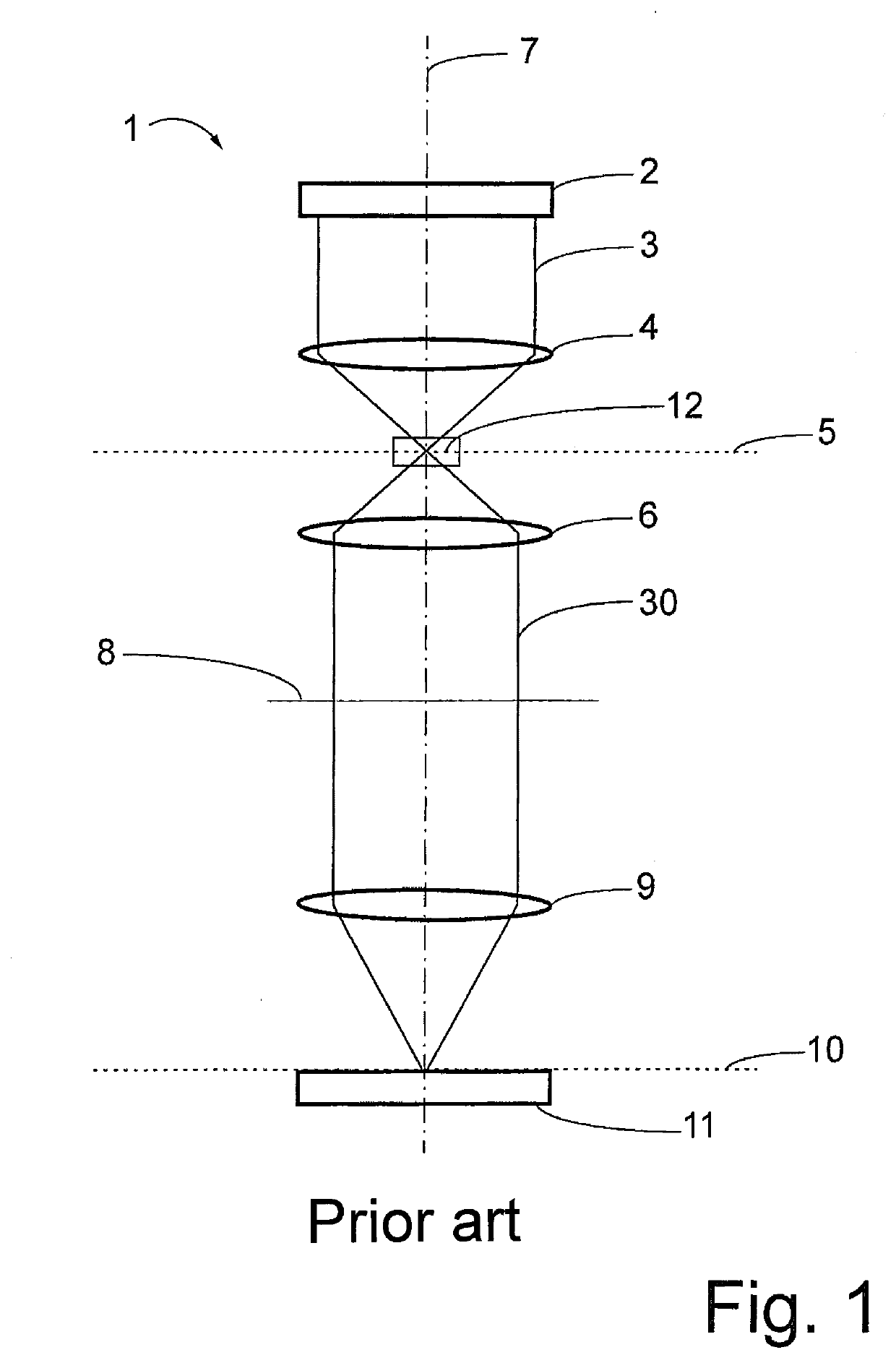
[0064]A microscope 1 designed according to the prior art for producing a contrast image is represented in FIG. 1 and has a light source 2 for providing an illumination radiation 3, a condenser 4 for focusing the illumination radiation 3 in an object plane 5, an objective unit 6 for collecting and imaging object radiation 30 obtained from the object plane 5 in the direction of an optical axis 7 of the microscope 1 in an image-side pupil 8, an imaging unit 9 for imaging the object radiation 30 in an image plane 10 and an acquisition unit 11 for the spatially resolved acquisition of image data in the image plane 10. The image data are brought about by the object radiation 30, because of the illumination radiation 3 passing through an object 12 that is optionally present in the object plane 5, and also because of it passing through the beam path of the microscope 1 i...


PUM


Abstract

A microscopy method, and a microscope for carrying out the method, in which an illumination radiation is directed through an object arranged in an object plane of a microscope, in order to image the object, image data of a first image of the object being acquired with a first configuration of the microscope and image data of a second image of the object being acquired with a second configuration of the microscope. Differences between the image data of the first image and the second image are determined and, in dependence on the determined differences, image data of a contrast image of the object is provided. In the first configuration, a phase mask that has at least one optical gradient transversely in relation to the optical axis of the microscope, by the effect of which a phase gradient of the illumination radiation passing through the phase mask is produced or can be produced, is arranged in an objective pupil of the microscope and, in the second configuration, the phase mask is removed from the objective pupil.

Description

RELATED APPLICATIONS[0001]The present application is a U.S. National Stage application of International PCT Application No. PCT / EP2016 / 076671 filed on Nov. 4, 2016 which claims priority benefit of German Application No. DE 10 2015 221 991.7 filed on Nov. 9, 2015, the contents of each are incorporated by reference in their entirety.FIELD OF THE INVENTION[0002]The invention relates to a microscopy method for determining a contrast image according to the preamble of claim 1 and to a microscope according to the preamble of claim 8.BACKGROUND OF THE INVENTION[0003]In order to be able to image low-contrast objects, particularly in light-optical microscopy, a phase-contrast method or a method of differential interference contrast (DIC) have been, for example, used. These require the arrangement of two expensive Wollaston or Nomarski prisms and two polarizers in the beam path. Moreover, a number of optical elements have to be introduced both into the illuminating beam path and the imaging b...

Claims


Application Information

Patent Timeline
IPC IPC(8): G02B21/36G02B21/14G02B21/08H04N7/18H04N5/225G06T3/40
CPCG02B21/086G06T3/40G02B21/367H04N5/2254G02B21/14H04N7/18H04N5/2256G02B21/0032G02B21/0056H04N23/55H04N23/56
Inventor KALKBRENNER, DR. THOMAS
Owner CARL ZEISS MICROSCOPY GMBH
Why Eureka
Try Eureka