
Noise damper for compressed air systems and a method for the production of same

Active Publication Date: 2020-08-27
KNORR-BREMSE SYST FUER NUTZFAHRZEUGE GMBH
View PDF0 Cites 0 Cited by
  • Summary
  • Abstract
  • Description
  • Claims
  • Application Information

AI Technical Summary

Benefits of technology

[0014]Optionally, the housing comprises, opposite the separating plate along the compressed-air stream, a base plate (exit plate or outlet plate) with a multiplicity of exit openings for the compressed-air stream, wherein the exit openings are formed in particular as a honeycomb pattern in the base plate. Here, the exemplary honeycomb structure offers very good mechanical stability together with a very good weight ratio. It is likewise possible for the housing to be formed such that no exit opening is closer to t

Problems solved by technology

Compressed-air systems often release large quantities of compressed air into the surroundings within an extremely short time.
This expansion process can produce considerable noises.
This is however often difficult to implement, because there is often not sufficient space available.
In the case of utility vehicles, the available space is increasingly limited, and it is scarcely possible to accommodate larger noise dampers.
Said system however has the disadvantage that it has a relatively high flow resistance for the compressed air.
The changes in direction can furthermore lead to blockages or instances of icing occurring within the noise-reducing material.
Specifically, in general, the compressed air has contaminants and/or a high moisture content, such that the sudden pressure drop leads to

Method used


Image

  • Noise damper for compressed air systems and a method for the production of same
  • Noise damper for compressed air systems and a method for the production of same
  • Noise damper for compressed air systems and a method for the production of same

Examples


Embodiment Construction

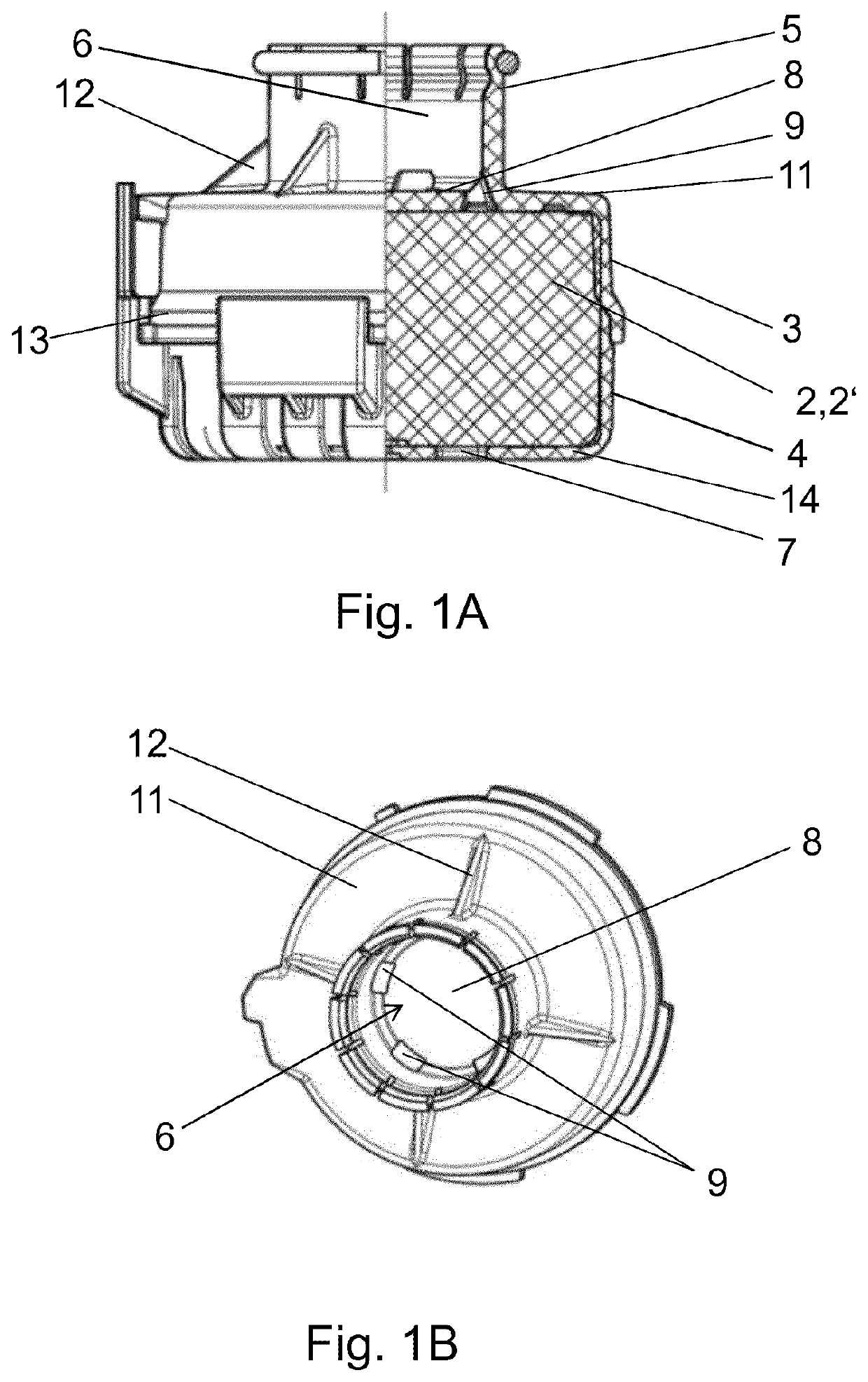
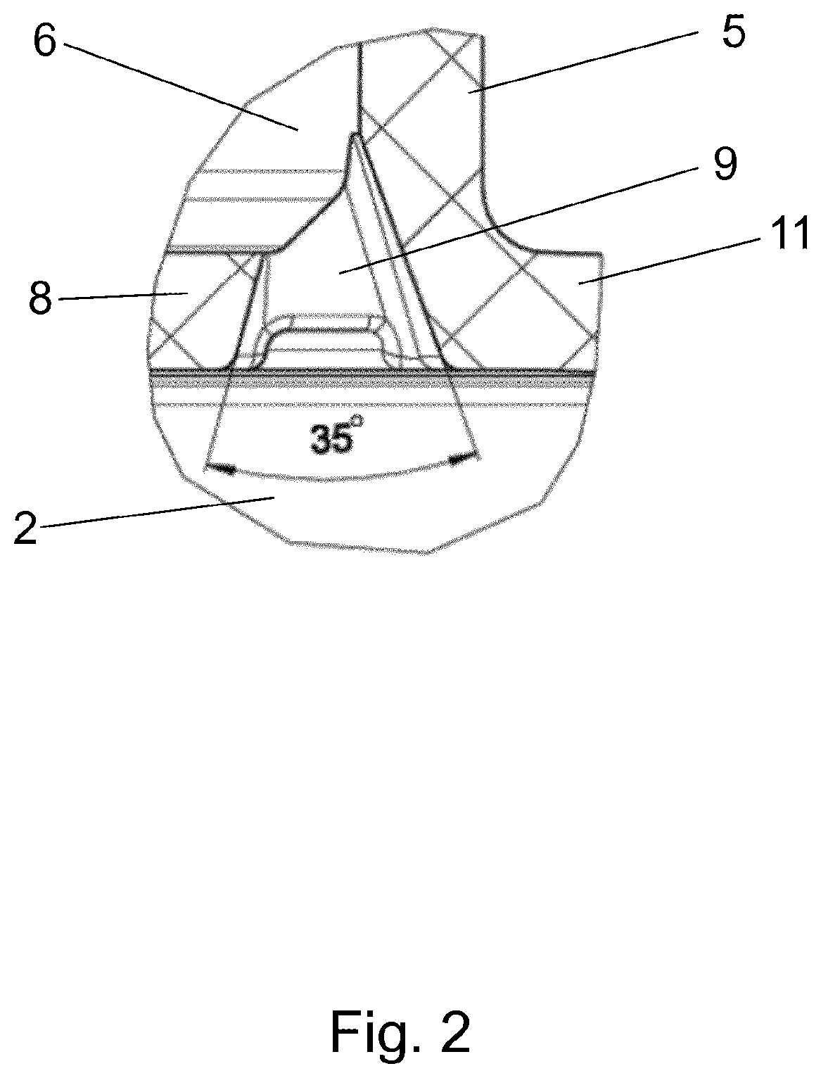
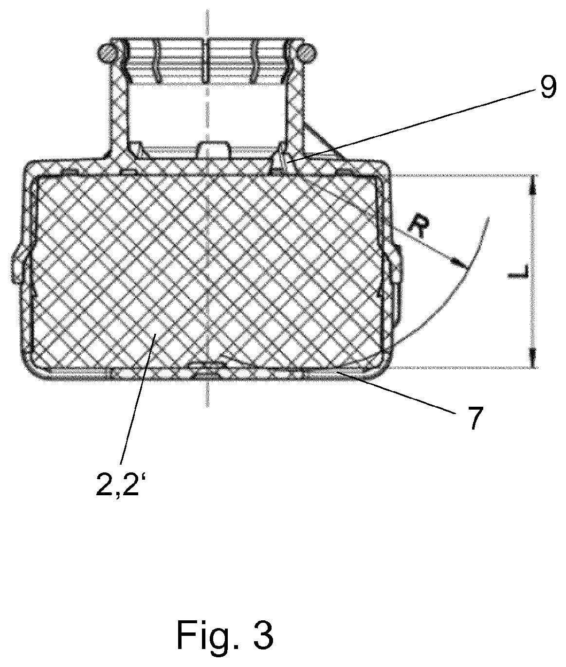
[0046]FIG. 1A shows an external view with a partial section through a noise damper according to an exemplary embodiment of the present invention. The noise damper is suitable for compressed-air systems, in particular for brake systems of utility vehicles, and comprises a housing 3, 4 with an inlet channel 6 for a compressed-air stream and comprises a chamber 2 for accommodating sound-damping material 2′. The inlet channel 6 and the chamber 2 are separated from one another, perpendicularly with respect to the compressed-air stream, by a separating plate 8 which, in an outer peripheral region of the compressed-air stream or of the inlet channel 6, has multiple openings 9 for introducing the compressed air into the chamber 2. In particular, the openings 9 may be formed in a regular manner only in the outer peripheral region, such that the separating plate 8 has no openings in its central region (for example in relation to the inlet channel 6).

[0047]The housing 3, 4 of the noise damper ...


PUM


Abstract

A noise damper for a compressed-air system, for a brake system of a utility vehicle, including: a housing having an inlet channel for a compressed-air stream and with a chamber for accommodating sound-damping material, in which the inlet channel and the chamber are separated, perpendicularly with respect to the compressed-air stream, by a separating plate which is closed in a central region and which, in an outer peripheral region of the compressed-air stream, has multiple openings for introducing the compressed air directly into the chamber. Also described are a related pneumatic brake system and method.

Description

FIELD OF THE INVENTION[0001]The present invention relates to a noise damper for compressed-air systems, to a compressed-air system, and to a method for producing noise dampers.BACKGROUND INFORMATION[0002]Compressed-air systems often release large quantities of compressed air into the surroundings within an extremely short time. This expansion process can produce considerable noises. In order to keep the noise emission at an admissible level, noise dampers are commonly required for compressed-air systems.[0003]The housing of such noise dampers may be connected directly to a pneumatic valve, for example by a bayonet fastener. One known system is discussed for example in EP 0 708 007 B1, wherein the valve body has an outlet channel which is partially integrated in the inlet channel of the noise damper unit. A further possibility consists in providing a channel-like intermediate component which, for example as part of the housing of the noise damper, provides a connection to the outlet ...

Claims


Application Information

Patent Timeline
IPC IPC(8): B60T17/00G10K11/162
CPCB60T17/008G10K11/161B60T15/36G10K11/172F15B21/008F15B2211/8855
Inventor SOVAGO, SZABOLCSTANCZOS, MIKLOSFEKETE, MARTONBUJDOSO, DANIEL
Owner KNORR-BREMSE SYST FUER NUTZFAHRZEUGE GMBH
Learn More