Supercharge Your Innovation With Domain-Expert AI Agents!

Aircraft landing gear uplock system

Active Publication Date: 2020-08-27
AIRBUS OPERATIONS LTD
View PDF4 Cites 2 Cited by
  • Summary
  • Abstract
  • Description
  • Claims
  • Application Information

AI Technical Summary

Benefits of technology

The present invention provides an aircraft with a reliable system to confirm the status of the landing gear's uplock and the capture pin. This system detects whether the hook is in its closed position and the capture pin is in its captured position, allowing for the identification of failure modes that may have previously been undeterminable. This ensures the safety and reliability of the aircraft. Additionally, the invention includes a target that is designed to be easily detectable, improving the accuracy of the sensor. The uplock is mounted to the aircraft structure, which may include a spherical bearing or a variable length strut with hydraulic dampener or spring, which assists with dealing with loads and relative movement that may arise from wing flexure.

Problems solved by technology

This may allow the detection of a previously hidden failure mode in which the hook (or the remnants thereof) remains in the closed position, but fails structurally such that the capture pin is released from the uplock.

Method used


Image

  • Aircraft landing gear uplock system
  • Aircraft landing gear uplock system
  • Aircraft landing gear uplock system

Examples


first embodiment

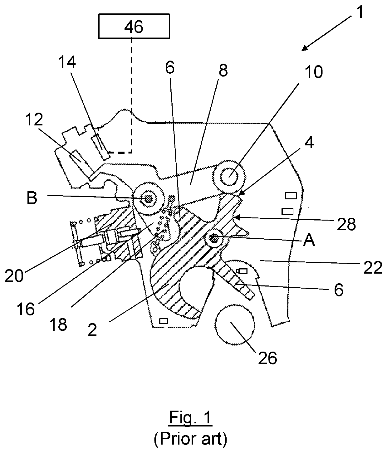
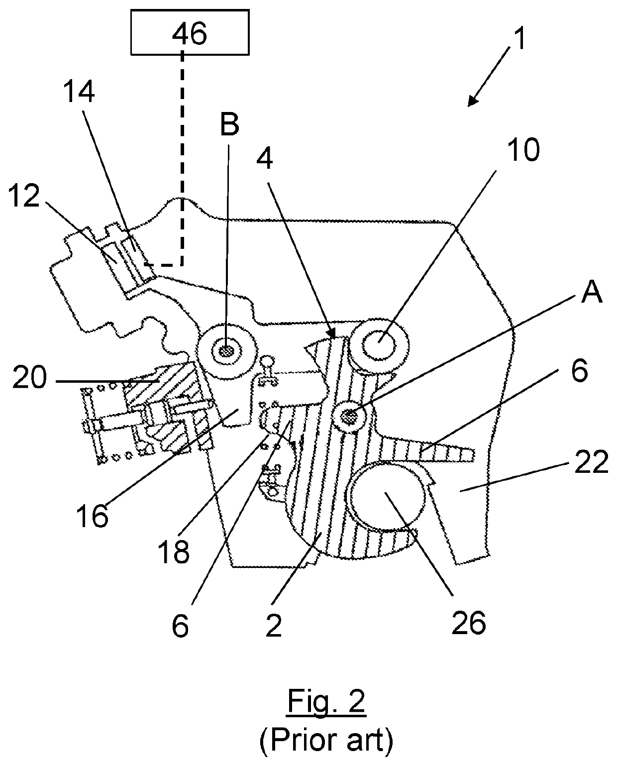
[0049]FIG. 4 shows a schematic view of a landing gear uplock 101 in an open and unlocked configuration. The uplock 101 has a main body 122 which is mounted to structure in the landing gear bay via a spherical bearing 130 and two sprung struts 132, 134 of variable length. This means of mounting of the uplock 101 allows for movement and flexure of the wings of the aircraft in flight to be accommodated without imposing unduly high loads on the uplock. Such load might otherwise be caused, as the landing gear moves relative to the uplock as a result of such movement / flexure. The uplock also includes guide plates 136 for guiding passage of the pin 126 into the uplock. The uplock 101 is otherwise very similar to the uplock 1 shown in FIGS. 1 and 2. As such, like reference numerals denote like elements (for example the uplock of FIG. 1 is labelled with reference numeral 1 and the uplock of FIG. 3 is labelled with reference numeral 101). It will be appreciated that an uplock contains other ...

second embodiment

[0058]In this second embodiment, two bespoke targets are provided, one (target 262) being mounted on a bracket 264 on the plate 227 which holds the capture pin 226, the other target (not shown) being mounted on a bracket (not shown) on the other plate. The targets are each made from 17-4 PH stainless steel, which is available from AK Steel. A proximity sensor for detecting the presence of each target is provided on the uplock, itself (only one such proximity sensor being shown in the Figs.). The uplock comprises an exterior casing which houses the hook 202. A proximity sensor 260 is mounted on the side of the exterior of the casing of the uplock 201 for detecting the presence of its paired (corresponding) target 262. It will be seen that as the landing gear moves towards the uplocks (FIGS. 12 to 14 in series), the target 262 moves towards its corresponding sensor 260. FIG. 14 shows the landing gear in the up and locked position. It will be seen that the proximity sensor 260 is align...


PUM


Abstract

An uplock for use with an aircraft landing gear is disclosed having a hook configured to engage a capture pin mounted on the landing gear. The hook is mounted for movement between a closed and locked position and an open and unlocked position. A proximity detector directly detects whether the pin is “up”. An uplock hook sensor detects when the hook is in the closed and locked position. The outputs of the proximity detector and the uplock hook sensor may be used to indicate the “up and locked” condition, i.e., landing gear up, and / or to indicate a fault. Such outputs may be provided by an associated device of an avionics system.

Description

BACKGROUND OF THE INVENTION[0001]The present invention concerns an uplock for an aircraft component. More particularly, but not exclusively, this invention concerns an uplock comprising a hook configured to receive a capture pin mounted on the aircraft component to be restrained. Thus, the invention concerns an uplock that holds an aircraft component in position by capturing a capture pin mounted on that component with a hook. The invention also concerns an uplock suitable for use with a retractable landing gear or a folding wing tip device.[0002]Typically, aircraft with retractable landing gear have an uplock which holds the gear in place in the landing gear bay when the landing gear has been retracted. FIGS. 1 and 2 show a schematic drawing of a typical uplock 1 in the (FIG. 1) open and (FIG. 2) locked configuration. The uplock comprises a hook 2 mounted to pivot about a point labelled A in FIG. 1. The hook 2 includes a cam surface 4 at the upper end of the hook 2 and an arm 6 ext...

Claims


Application Information

Patent Timeline
IPC IPC(8): B64C25/28B64D45/00H04L29/08
CPCE05B2047/0069H04L67/12B64D45/0005B64C25/28E05B81/14B64C25/26
Inventor MCCAMBRIDGE, OLIVERBRIGHTON, TREVOR ANTHONY
Owner AIRBUS OPERATIONS LTD
Features
  • R&D
  • Intellectual Property
  • Life Sciences
  • Materials
  • Tech Scout
  • Unparalleled Data Quality
  • Higher Quality Content
  • 60% Fewer Hallucinations
Learn More