Supercharge Your Innovation With Domain-Expert AI Agents!

Closure mechanism vacuum chamber isolation device and sub-system

a vacuum chamber and isolation device technology, applied in the direction of valves, mechanical devices, engine components, etc., can solve the problems of frequent maintenance, degradation of the sealing mechanism, and the isolation device is not suitable for use in the processing system

Active Publication Date: 2020-08-27
APPLIED MATERIALS INC
View PDF0 Cites 0 Cited by
  • Summary
  • Abstract
  • Description
  • Claims
  • Application Information

AI Technical Summary

Benefits of technology

The present invention provides an isolation device and a system for processing a substrate. The isolation device includes a body with a first flow aperture, a lower plate with a second flow aperture, and a cover plate with an opening. The seal plate is at least partially defined by the body, lower plate, and cover plate. A shaft is disposed through the opening in the cover plate and a seal plate is disposed in the seal plate volume, which can rotate about an axis of the shaft. The seal plate covers the first flow aperture and the second flow aperture when closed. The system for processing a substrate includes a remote plasma source, a process chamber, and an isolation device between them. The isolation device is used to create a vacuum and prevent contamination during substrate processing.

Problems solved by technology

Conventional remote plasma source isolation devices, where a simple valve is utilized in a flowline between the remote plasma source and the port, often suffer from degradation of the sealing mechanism thereof due to exposure of the sealing mechanism to the gas radicals, gas ions, or both from the remote plasma source, or from exposure to the a process chemistry in the process volume of the process chamber.
Likewise, some process gases are corrosive or erosive of seal materials, and a traditional valve may need frequent servicing when exposed to these gases.
As a result, frequent maintenance is needed to repair or replace the sealing mechanism to maintain functionality.
These maintenance operations often involve lengthy outages of the process chamber resulting in reduced utilization of the process chamber.

Method used


Image

  • Closure mechanism vacuum chamber isolation device and sub-system
  • Closure mechanism vacuum chamber isolation device and sub-system
  • Closure mechanism vacuum chamber isolation device and sub-system

Examples


Embodiment Construction

[0015]The embodiments described herein relate to an apparatus for isolating chambers within a processing system from a flow line. Although the description hereof includes a remote plasma chamber, the apparatus is useful for isolating any flow line into, or out of, a substrate process chamber.

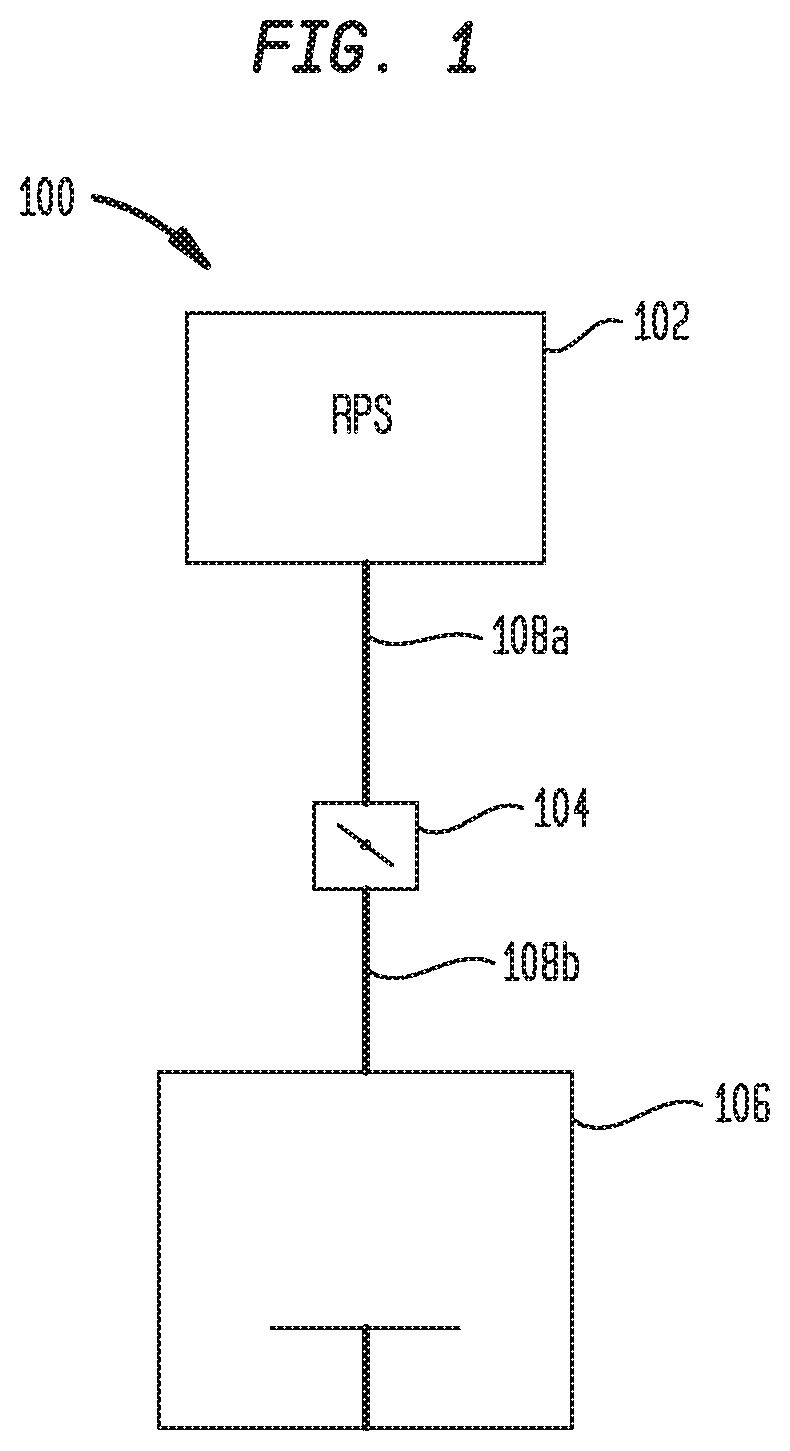
[0016]FIG. 1 is a schematic of an exemplary processing apparatus utilizing a remote plasma source. In FIG. 1, a processing apparatus 100 comprises a remote plasma source 102 coupled to a process chamber 106 by conduits 108a, 108b. An isolation device 104, such as a valve, is disposed between the remote plasma source 102 and the process chamber 106. The isolation device 104 is in fluid communication with the remote plasma source 102 and the process chamber 106 through the conduits 108a, 108b. During processing, passage of fluid, i.e., a gas, through the isolation device 104 may be interrupted to isolate the process chamber 106 from the remote plasma source 102. By opening the isolation device 104...


PUM


Abstract

The present disclosure generally relates to an isolation device for use in processing systems. The isolation device includes a body having a flow aperture formed therethrough. In one embodiment, the isolation device is disposed between a remote plasma source and a process chamber. A closure mechanism is pivotally disposed within the body. The closure mechanism can be actuated to enable or disable fluid communication between the remote plasma source and the process chamber. In one embodiment, the closure mechanism includes a shaft and a seal plate coupled to the shaft. A cross-arm is coupled to the shaft opposite the seal plate. The cross-arm is configured to selectively rotate the shaft and the seal plate of the closure mechanism.

Description

BACKGROUNDField[0001]Embodiments of the present disclosure generally relate to an isolation device for use in a processing system.Description of the Related Art[0002]In manufacturing of microelectronic devices such as semiconductor devices, gas sources supply process gases into a process volume of a process chamber. Additionally, in some process chambers or process applications, remote plasma sources are used to provide gas radicals, gas ions, or both to a process chamber in which a process is being carried out on a substrate, or to the process chamber to clean deposits from the interior surfaces thereof. The remote plasma source is generally connected to the process chamber through a port disposed through the body of the process chamber. In order to isolate the remote plasma source from the process chamber, an isolation device, such as a valve, is disposed between the remote plasma source and the process chamber. During operations utilizing the remote plasma source to supply gas ra...

Claims


Application Information

Patent Timeline
Patent Type & Authority Applications(United States)
IPC IPC(8): H01J37/32F16K3/06F16K3/02F16K31/04F16K51/02
CPCH01J37/32623H01J37/32357F16K3/06H01J2237/024F16K3/0218F16K51/02F16K31/041F16K37/0041H01J37/32H01J37/3288
Inventor NGUYEN, TUAN ANH
Owner APPLIED MATERIALS INC
Features
  • R&D
  • Intellectual Property
  • Life Sciences
  • Materials
  • Tech Scout
  • Unparalleled Data Quality
  • Higher Quality Content
  • 60% Fewer Hallucinations
Learn More