This helps you quickly interpret patents by identifying the three key elements:
Problems solved by technology
Method used
Benefits of technology
Benefits of technology
The present invention provides a webbing take-up device that can efficiently transmit kinetic energy from the moving member to the rotating body, reducing the rotation force of the spool when taking up the webbing onto the spool. The device includes an abutted portion on the rotating body placement section or the wall portion closest to the spool, restricting the rotating body from moving in the axial direction. Additionally, a part of the rotating body or spool can deform when load acts on the webbing, enabling the spool to rotate in the pull-out direction with respect to the rotating body. The device also includes a torsion shaft that can undergo torsional deformation, allowing the spool to rotate in the pull-out direction with respect to the rotating body. The object of the invention is to stabilize the load on the webbing and the spool, reducing friction and improving the efficiency and stability of the webbing take-up device.
Problems solved by technology
However, if the rotating body moves in a rotation axis direction of the rotating body when the moving member engages with the rotating body, it is conceivable that kinetic energy of the moving member might not be efficiently transmitted to the rotating body.
Method used
Image
Click on the blue label to locate the original text in one second.
Reading with bidirectional positioning of images and text.
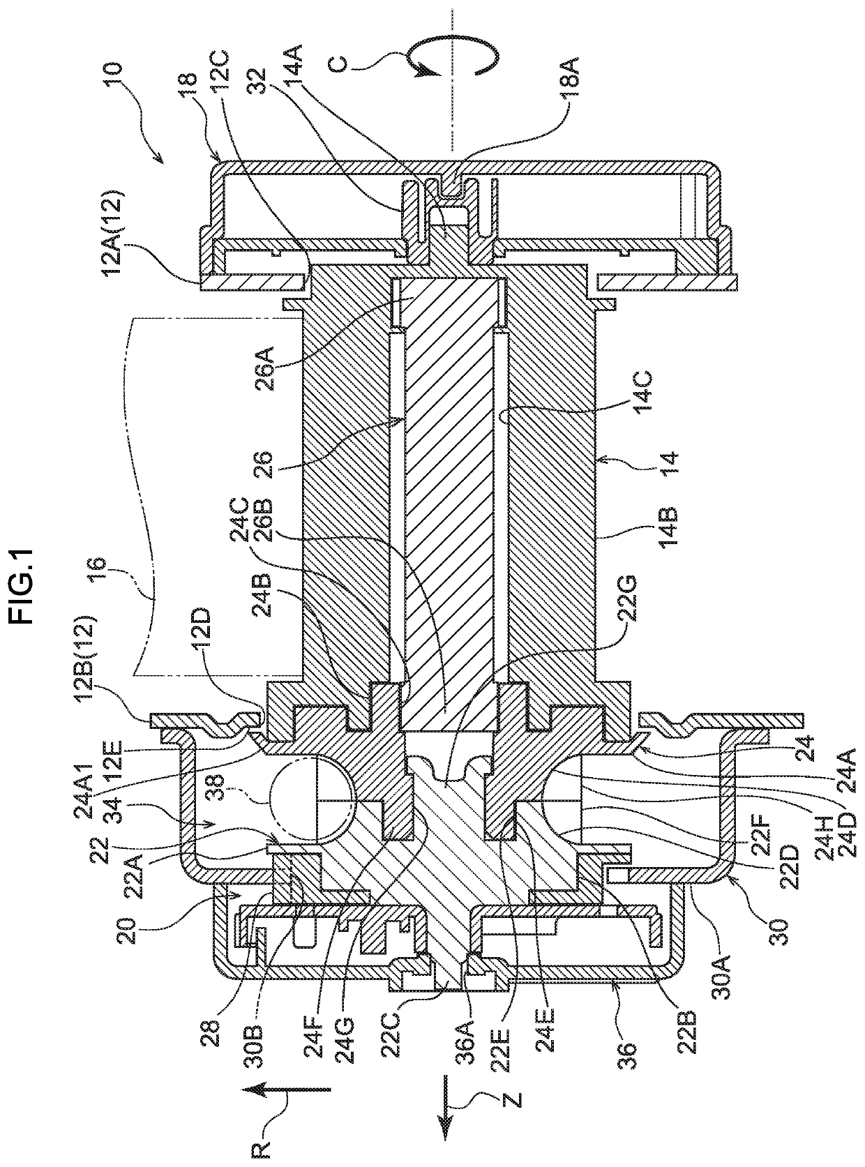
[0022]Explanation follows regarding a webbing take-up device according to a first exemplary embodiment of the present invention, with reference to FIG. 1. Note that in the drawings, the arrow Z direction, the arrow R direction, and the arrow C direction respectively indicate a rotation axis direction, a rotation radial direction, and a rotation-circumferential direction of a spool, as appropriate. In the following explanation, unless specifically stated otherwise, reference simply to an axial direction, radial direction, or circumferential direction refers respectively to the rotation axis direction, the rotation radial direction, or the rotation-circumferential direction of the spool.
[0023]As illustrated in FIG. 1, a webbing take-up device 10 includes a metal frame 12. For example, the frame 12 is fixed to a pillar configuring vehicle body framework, or to a seat cushion frame configuring framework of a vehicle seat in a vehicle. The frame 12 includes a ...
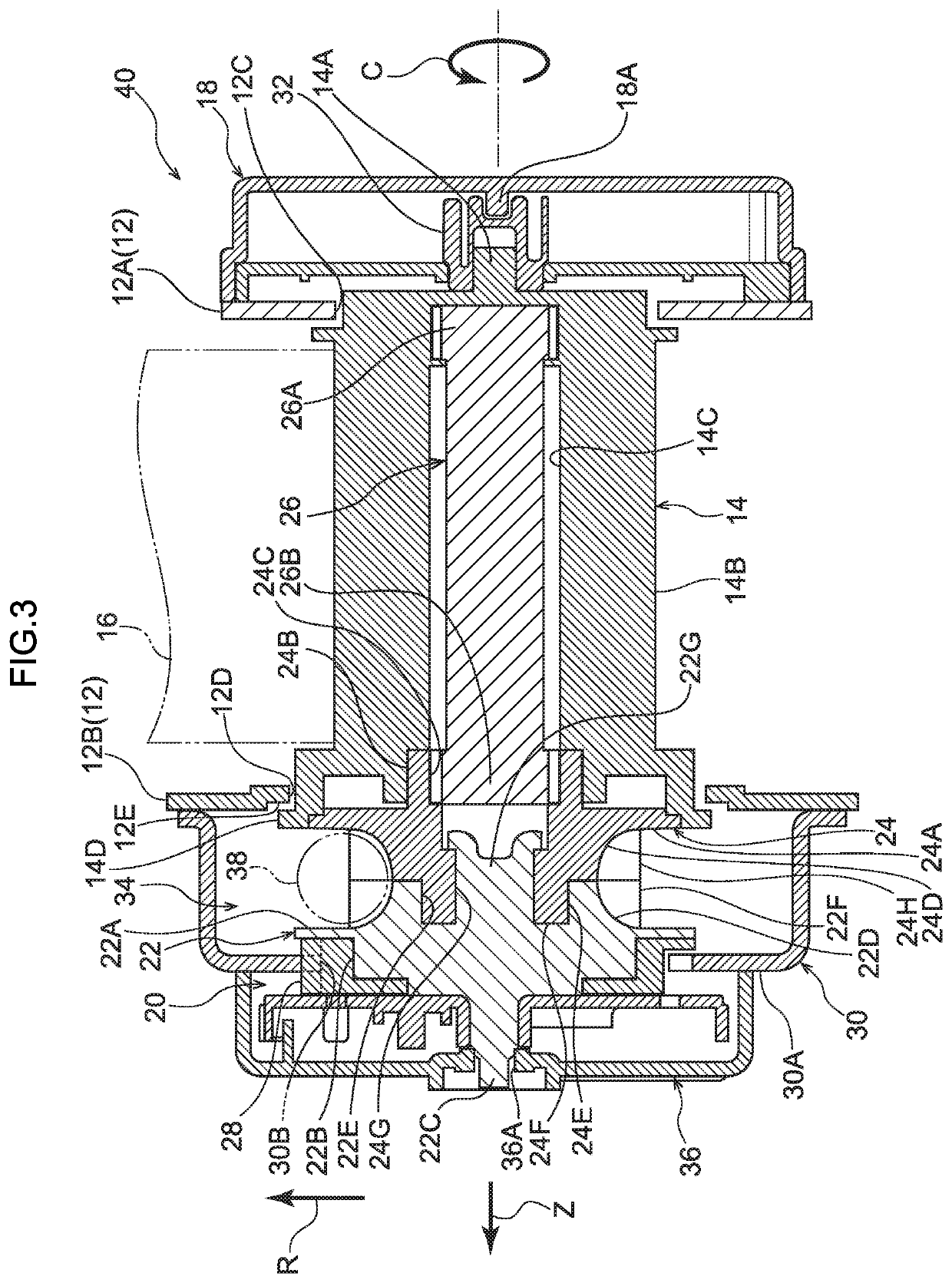
[0051]Explanation follows regarding a webbing take-up device according to a second exemplary embodiment of the present invention, with reference to FIG. 3. Note that members and portions corresponding to those in the webbing take-up device 10 according to the first exemplary embodiment are appended with the same reference numerals as in the above exemplary embodiment, and explanation regarding these members and portions may be omitted.
[0052]As illustrated in FIG. 3, a feature of a webbing take-up device 40 of the present exemplary embodiment is that the spool 14 is provided with a portion that abuts the abutted portion 12E, this being the portion peripheral to the edge of the insertion hole 12D formed in the leg plate 12B of the frame 12.
[0053]A spool-side flange 14D is formed projecting toward the radial direction outer side at the one axial direction side end portion of the spool 14. An external diameter of the spool-side flange 14D is greater than the ...
PUM
Abstract
A webbing take-up device includes a spool. The webbing take-up device also includes a lock base and a coupling member that are provided so as to rotatable as an integral unit with the spool, and that engage with a rack so as to be rotated and to rotate the spool in a take-up direction when the rack is moved. The webbing take-up device further includes a rack housing section that includes a pair of wall spaced apart from each other in a rotation axis direction of the lock base and the coupling member so as to form a space in which the lock base and the coupling member are disposed. The rack housing section is provided with an abutted portion that is abutted by a part of the coupling member so as to restrict the lock base and the coupling member from moving in the rotation axis direction.
Description
TECHNICAL FIELD[0001]The present invention relates to a webbing take-up device.BACKGROUND ART[0002]Japanese National-Phase Publication 2012-509808 discloses a webbing take-up device including a spool that takes up a webbing, a rotating body that is provided so as to be capable of rotating as an integral unit with the spool and that is rotated in a vehicle emergency so as to rotate the spool in a take-up direction, and a moving member that is moved so as to engage with the rotating body and rotate the rotating body.[0003]However, if the rotating body moves in a rotation axis direction of the rotating body when the moving member engages with the rotating body, it is conceivable that kinetic energy of the moving member might not be efficiently transmitted to the rotating body.SUMMARY OF INVENTIONTechnical Problem[0004]In consideration of the above circumstances, an object of the present disclosure is to obtain a webbing take-up device capable of restricting rotation axis direction move...
Claims
Application Information
Patent Timeline
Application Date:The date an application was filed.
Publication Date:The date a patent or application was officially published.
First Publication Date:The earliest publication date of a patent with the same application number.
Issue Date:Publication date of the patent grant document.
PCT Entry Date:The Entry date of PCT National Phase.
Estimated Expiry Date:The statutory expiry date of a patent right according to the Patent Law, and it is the longest term of protection that the patent right can achieve without the termination of the patent right due to other reasons(Term extension factor has been taken into account ).
Invalid Date:Actual expiry date is based on effective date or publication date of legal transaction data of invalid patent.

