
Power-assisted steering oil cylinder with stroke unloading valve

A technology of steering power cylinder and unloading valve, which is applied in the field of power cylinders and can solve the problems of short service life and low stability of the limit structure

Pending Publication Date: 2022-02-25
CHONGQING CAFF AUTOMOTIVE BRAKING & STEERING SYST
View PDF0 Cites 0 Cited by
  • Summary
  • Abstract
  • Description
  • Claims
  • Application Information

AI Technical Summary

Problems solved by technology

[0003] The present invention intends to provide a steering power cylinder with a stroke unloading valve to solve the problems of low stability and short service life of the steering system and the limit structure when the vehicle uses the power cylinder in the prior art

Method used


Image

  • Power-assisted steering oil cylinder with stroke unloading valve
  • Power-assisted steering oil cylinder with stroke unloading valve
  • Power-assisted steering oil cylinder with stroke unloading valve

Examples


Embodiment 1

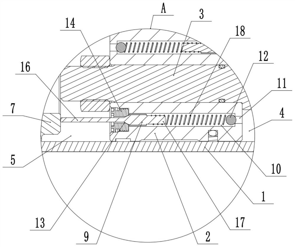
[0035] Embodiment one is basically as attached figure 1 with figure 2 Shown: the power steering cylinder with a stroke unloading valve, including a cylinder body 1 and a piston 2 that is slidably connected in the cylinder body 1. The piston rod 3 and the piston 2 divide the cylinder 1 into a rod chamber 4 and a rodless chamber 5. Two oil pipes 6 are connected to the cylinder body 1, and the two oil pipes 6 communicate with the rod chamber 4 and the rodless chamber 5 respectively. , the oil pipe 6 can be used to feed high-pressure hydraulic oil into the rod chamber 4 or the rodless chamber 5; at the same time, the left end and the right end of the cylinder body 1 are fixedly connected with end caps through threads, and for the convenience of distinction, the left end cap is The left end cap 7, the right end cap is the right end cap 8.

[0036] combine figure 2 with image 3 The piston 2 is provided with at least two flow passages respectively communicating with the rod ch...

Embodiment 2

[0045] The difference between embodiment two and embodiment one is: as Figure 5 As shown, the large-diameter section 10 is connected with a horizontally arranged slide bar 19 through an interference fit. The slide bar 19 is coaxially arranged with the push rod 16 and the right end of the push rod 16 is located in the slide bar 19. The left end of the slide bar 19 Extend outside the left side of piston 2, and the left end of push rod 16 extends outside the left end of slide rod 19; A communication gap is formed between the outer walls of the push rods 16, and the inner hole of the slide rod 19 is provided with a second mating inclined surface near the right end to the sealing inclined surface 13 at the left end of the control rod 9.

[0046] When the second mating inclined surface is in contact with the sealing inclined surface 13, the hydraulic oil at the position of the support spring 18 in the large-diameter section 10 cannot flow to the left through the communication groov...


PUM


Abstract

The invention relates to the technical field of power-assisted oil cylinders, and discloses a power-assisted steering oil cylinder with a stroke unloading valve. The oil cylinder comprises a cylinder body and a piston connected in the cylinder body in a sliding manner, the piston divides the cylinder body into a rod cavity and a rodless cavity, the two ends of the cylinder body are fixedly connected with end covers, the piston is provided with at least two runners communicated with the rod cavity and the rodless cavity, a control mechanism used for enabling the flow channel to be opened and closed is connected in each flow channel, a first trigger mechanism is connected between at least one control mechanism and the end cover on one side of the rodless cavity, and a second trigger mechanism is connected between at least one control mechanism and the end cover on one side of the rod cavity. The problems that a steering system and a limiting structure are low in stability and short in service life when a vehicle uses a power-assisted oil cylinder in the prior art are solved.

Description

technical field [0001] The invention relates to the field of booster cylinders, in particular to a steering booster cylinder with a stroke unloading valve. Background technique [0002] At present, large-scale mechanical vehicles are mostly equipped with a clutch booster system, which assists the clutch operation through the booster cylinder, alternately feeds oil through the oil inlet and outlet, and pushes the piston to move to achieve steering assistance. For existing automobile steering systems, in order to control the steering range of the steering system, a mechanical limit structure is usually set to limit the steering range (for example, using a limit screw to limit the steering angle of the steering system), so when the car turns to At the limit position, the steering system will collide hard with the limit structure. If the steering system frequently collides hard with the limit structure, it will easily affect the stability of the steering system and the limit str...

Claims


Application Information

Patent Timeline
IPC IPC(8): F15B15/14F15B15/20
CPCF15B15/14F15B15/20F15B15/1447
Inventor 刘云川邱小冲钟威张磊李泓利梁光维
Owner CHONGQING CAFF AUTOMOTIVE BRAKING & STEERING SYST
Learn More