System, method, and apparatus for clamping

a technology of clamping system and clamping method, applied in the direction of cable arrangement between relatively moving parts, process and machine control, instruments, etc., can solve the problems of insufficient tightening, risk of human error, and rare redundancy

Active Publication Date: 2020-09-03
DEKA PROD LLP
View PDF12 Cites 42 Cited by
  • Summary
  • Abstract
  • Description
  • Claims
  • Application Information

AI Technical Summary

Benefits of technology

[0348]In one example embodiment, the handles and gears may be configured to permit slight initial rotational movement of the handles in advance of subsequent rotational movement of the grippers, when moving the first and second handles from the first position to the second position. Similarly, the handles and gears may be configured to permit slight additional rotational movement of the handles following the stoppage of the rotational movement of the grippers, when moving the first and second handles from the second position back to the first position. The initial slight rotational movement of the handles may perform an unlocking function, freeing the grippers to move.

Problems solved by technology

They are often expensive, so redundancy is rarely possible, and a given device will often need to be moved to a different patient after a treatment is completed.
Such positioning and adjustment faces a number of constraints, for example, it can be time consuming, there is risk of cross-threading, there is risk of human error (i.e. not tightening enough) etc.
Furthermore, the at least one mount may be hingably coupled to the support member.
Similarly, the power system may be configured to receive unbalanced alternating-current power and to supply direct-current power to the respective connector of the at least one mount.
Displacement of the at least one handle may cause the displacement of the at least one gear plate.

Method used


Image

  • System, method, and apparatus for clamping
  • System, method, and apparatus for clamping
  • System, method, and apparatus for clamping

Examples


Embodiment Construction

Clamp Mechanisms

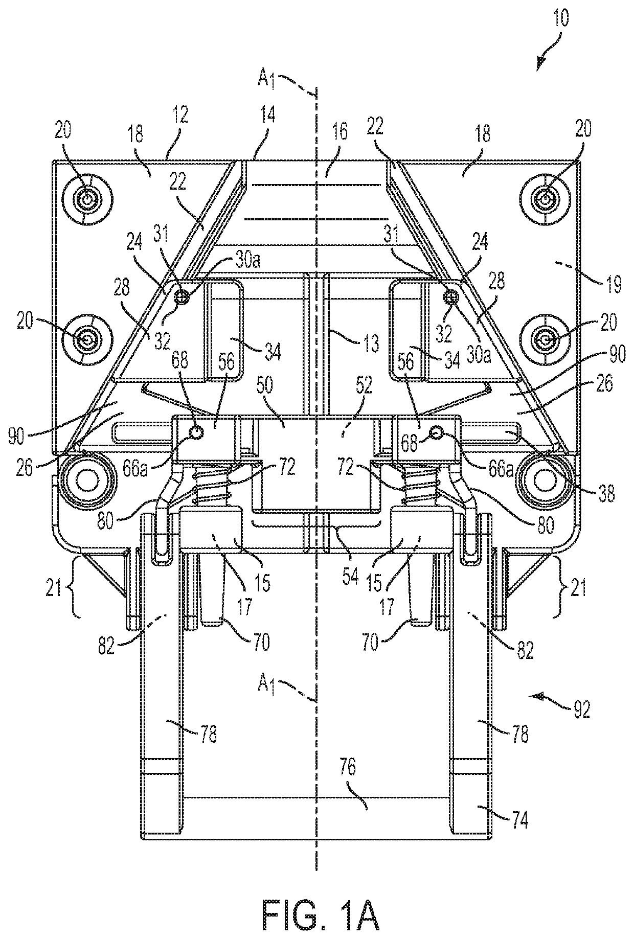
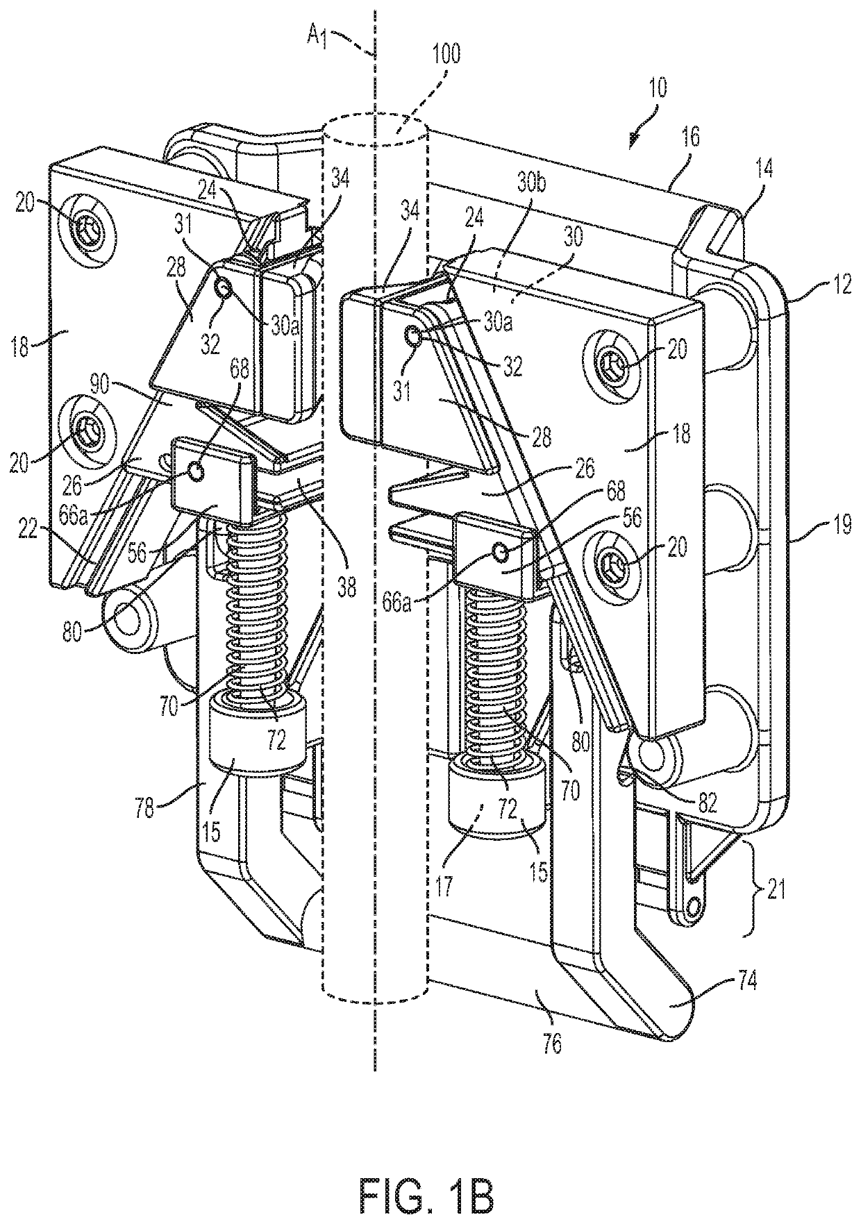
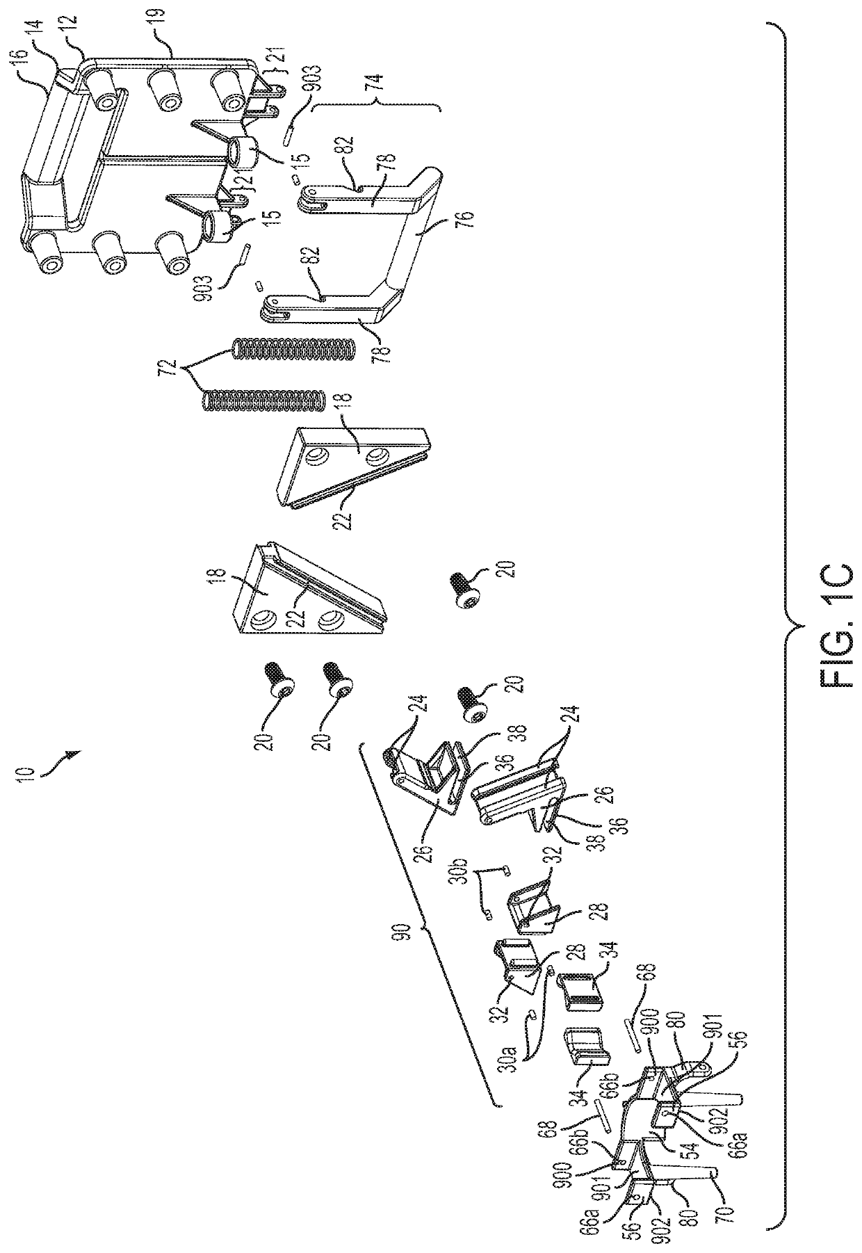
[0484]In one example embodiment, as shown in FIGS. 1A-1E, a clamp apparatus 10 is depicted. The clamp apparatus 10 comprises a housing 12. In the shown embodiment, the housing 12 has a back plate 14, which is generally planar. On one portion of the back plate 14 is a raised grip 16 extending away from the housing 12. The grip 16 affords the user ease of movement along a clamped object 100 generally extending along an axis A1. The grip 16 is also meant to aid in carrying. The grip 16 may be made of the same material as the rest of the housing 12, may be made of a different material, or may be made of a combination thereof. Possible materials may include, but are not limited to, rubber, polymer, composite, metal, plastic, foam, etc. Additionally, the grip 16 may comprise ergonomic finger groves, nubs, a ribbed texture, a honeycombed texture, etc.

[0485]The rear of the back plate 14 may also feature any of a variety of mechanisms 19 (not shown) to attach a load to the cl...


PUM


Abstract

A clamp apparatus is disclosed that includes a body, first and second actuators, first, second, third and fourth gear sets, first and second movable grippers, and at least one leaf spring. The first gear set is coupled to the first actuator and the second gear set is coupled to the second actuator. The first gear set engages the second gear set. The first and second movable grippers are each operatively coupled to the body. The third gear set is coupled to the first movable gripper and the fourth gear set is coupled to the second movable gripper. The third gear set operatively engages the fourth gear set. The leaf spring engages with the third gear set and the fourth gear set to urge the first movable gripper and the second movable gripper toward a clamped position.

Description

CROSS REFERENCE TO RELATED APPLICATION[0001]This application is a continuation of U.S. patent application Ser. No. 15 / 782,451, filed Oct. 12, 2017 and entitled System, Method, and Apparatus for Clamping, which will be U.S. Pat. No. 10,655,779, issuing on May 19, 2020 (Attorney Docket No. U38), which is a continuation of U.S. patent application Ser. No. 14 / 956,648, filed Dec. 2, 2015 and entitled System, Method, and Apparatus for Clamping, now U.S. Pat. No. 10,082,241, issued Sep. 25, 2018 (Attorney Docket No. Q69), which is a Non-Provisional application of U.S. Provisional Patent Application Ser. No. 62 / 086,356, filed Dec. 2, 2014, entitled System, Method, and Apparatus for Clamping (Attorney Docket No. M25), which is herein incorporated by reference in its entirety.[0002]U.S. patent application Ser. No. 14 / 956,648 is also a continuation-in-part of U.S. patent application Ser. No. 14 / 137,562, filed Dec. 20, 2013 and entitled System, Method, and Apparatus for Clamping, now U.S. Pat. ...

Claims


Application Information

Patent Timeline
Patent Type & Authority Applications(United States)
IPC IPC(8): F16M13/02H02G11/00A61M5/14A61M39/28A61M5/168
CPCY10T403/1624H02G11/00F16B2/12A61M5/1415A61M39/28F16B2/06A61M5/1414A61M5/16813F16M13/022
Inventor JANWAY, JEFFREY M.GRAY, LARRY B.GILL, MATTHEW RICHARDLANIGAN, RICHARD J.FRIEDRICH, THOMAS A.FICHERA, STEPHEN L.KERWIN, JOHN M.SABIN, ERIK N.KAMEN, DEAN
Owner DEKA PROD LLP
Why Eureka
Try Eureka