Double-sided imaging light guide

a light guide and double-sided technology, applied in the field can solve the problems of bulk, weight, and overall cost, and achieve the effect of reducing the number of optical light guides

Active Publication Date: 2020-09-03
VUZIX
View PDF0 Cites 20 Cited by
  • Summary
  • Abstract
  • Description
  • Claims
  • Application Information

AI Technical Summary

Benefits of technology

[0008]It is an object of the present disclosure to advance the art of image presentation when using compact head-mounted devices and similar imaging apparatus. Advantageously, embodiments of the present disclosure provide an improved double-sided beam expander capable of handling two color channels within a single thickness of substrate.

Problems solved by technology

Although conventional light guide mechanisms have provided a significant reduction in bulk, weight, and overall cost of display optics, there are still issues to resolve.
Cross-talk can lead to disparity between the color image data and the displayed color, and can also be a cause of objectionable color shifts, perceptible across the image field.
Stacking, however, leads to thicker devices, adds weight, reduces brightness, and has not provided highly satisfactory results.

Method used


Image

  • Double-sided imaging light guide
  • Double-sided imaging light guide
  • Double-sided imaging light guide

Examples


Embodiment Construction

[0028]The present description is directed in particular to elements forming part of, or cooperating more directly with, apparatus in accordance with the invention. It is to be understood that elements not specifically shown or described may take various forms well known to those skilled in the art.

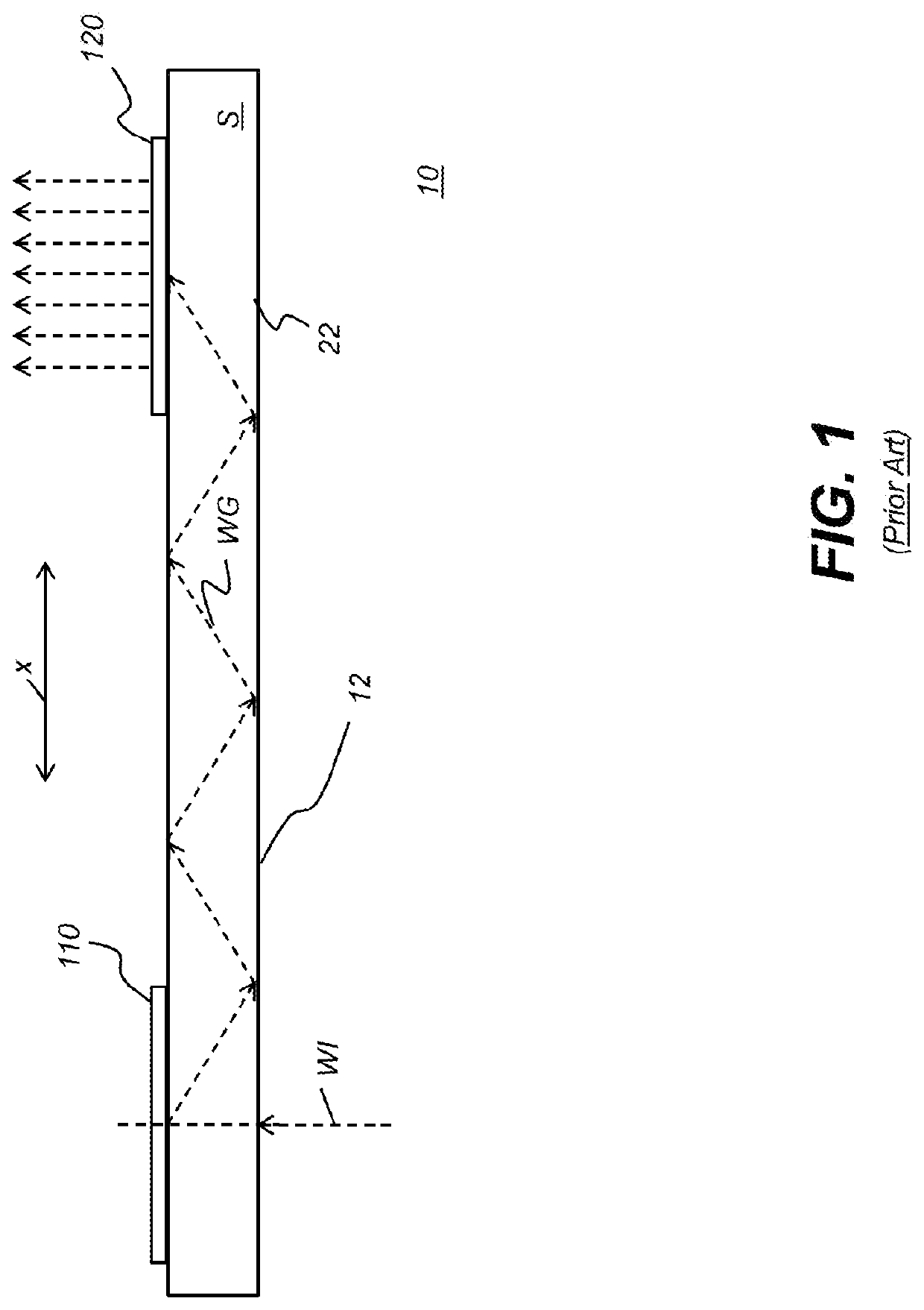
[0029]Where they are used herein, the terms “first”, “second”, and so on, do not necessarily denote any ordinal, sequential, or priority relation, but are simply used to more clearly distinguish one element or set of elements from another, unless specified otherwise. The terms “top” and “bottom” do not necessarily designate spatial position but provide relative information about a structure, such as to distinguish opposing surfaces of a planar (flat) waveguide.

[0030]In the context of the present disclosure, the terms “viewer”, “operator”, “observer”, and “user” are considered to be equivalent and refer to the person who wears the HMD viewing device.

[0031]As used herein, the term “energizab...


PUM


Abstract

An imaging light guide has waveguide for conveying image-bearing light beams from an image source to an eyebox within which a virtual image can be viewed. First and second in-coupling diffractive optics direct first and second sets of the image-bearing light beams into the waveguide along different first and second paths. First and second turning diffractive optics disposed along the respective paths expand the image-bearing light beams of the first and second sets in a first dimension and direct the expanded image-bearing light beams of the first and second sets to first and second out-coupling diffractive optics. The first and second out-coupling diffractive optics further expand the image-bearing light beams of the two sets in a second dimension and direct the further expanded image-bearing light beams of the two sets from the waveguide toward the eyebox.

Description

TECHNICAL FIELD[0001]This invention generally relates to optical light guides for conveying image-bearing light to a viewer particularly for use in video eyewear or augmented or virtual reality near-eye displays.BACKGROUND OF THE INVENTION[0002]Head-Mounted Displays (HMDs), which include near eye displays in a form resembling conventional eyeglasses or sunglasses, are being developed for a range of diverse uses, including military, commercial, industrial, fire-fighting, and entertainment applications. For many of these applications, there is particular value in forming a virtual image that can be visually superimposed over the real-world image that lies in the field of view of the HMD user. Light guides incorporating various types of waveguides relay image-bearing light to a viewer in a narrow space, acting as exit-pupil expanders for redirecting the virtual image to the viewer's pupil and enabling this superposition function.[0003]In the conventional light guide, collimated angular...

Claims


Application Information

Patent Timeline
Patent Type & Authority Applications(United States)
IPC IPC(8): G02B27/01F21V8/00G02B27/42
CPCG02B2027/0112G02B2027/0125G02B27/0172G02B2027/0174G02B6/0026G02B27/4277G02B6/005G02B2027/0178G02B27/0081
Inventor SCHULTZ, ROBERT J.TRAVERS, PAUL J.
Owner VUZIX
Why Eureka
Try Eureka