Projector as collimator light

a collimator and projector technology, applied in the field of radiographic imaging, can solve the problems of difficult to effectively use a grid for reducing the scattering effect, the receiver itself may not be visible to the technician, and complicate the alignment task of portable systems, so as to improve the setup and operation of the x-ray system

Active Publication Date: 2012-02-16
CARESTREAM HEALTH INC
View PDF1 Cites 38 Cited by
  • Summary
  • Abstract
  • Description
  • Claims
  • Application Information

AI Technical Summary

Benefits of technology

[0020]An object of the present invention is to advance the art of radiographic imaging by providing apparatus and methods to aid in alignment and proper positioning of the radiation source relative to a subject. A related object of the present invention is to provide a collimator light that shows the relative size and spread of an x-ray beam that is to be used for imaging and provides additional information that can be used to help improve setup and operation of the x-ray system.

Problems solved by technology

The receiver itself, however, may not be visible to the technician once it is positioned behind the patient.
This complicates the alignment task for portable systems, requiring some method for measuring SID, tilt angle, and centering, and making it more difficult to use a grid effectively for reducing the effects of scatter.
Because of this added complexity with a portable radiography system, the technician may choose not to use a grid; the result without a grid, however, is typically a lower-quality image.
However, complex mechanical solutions of this type tend to reduce the overall flexibility and portability of these x-ray systems.
Another type of approach, such as that proposed in U.S. Pat. No. 6,422,750 entitled “Digital X-ray Imager Alignment Method” to Kwasnick et al. uses an initial low-exposure pulse for detecting the alignment grid; however, this method would not be suitable for portable imaging conditions where the receiver must be aligned after it is fitted behind the patient.
This arrangement is less than desirable for portable imaging systems that allow a variable SID.
Tilt sensing, as has been conventionally applied and as is used in the device described in U.S. Pat. No. 7,156,553 entitled “Portable Radiation Imaging System and a Radiation Image Detection Device Equipped with an Angular Signal Output Means” to Tanaka et al. and elsewhere, does not provide sufficient information on cassette-to-radiation source orientation, except in the single case where the cassette lies level.
More complex position sensing devices can be used, but can be subject to sampling and accumulated rounding errors that can grow worse over time, requiring frequent resynchronization.
The conventional collimator light, however, does not provide information other than to show the relative beam size due to collimator blade settings.

Method used


Image

  • Projector as collimator light
  • Projector as collimator light
  • Projector as collimator light

Examples


Embodiment Construction

[0046]The following is a description of exemplary embodiments of the invention, reference being made to the drawings in which the same reference numerals identify the same elements of structure in each of the several figures.

[0047]In the context of the present disclosure, the term “imaging receiver”, or more simply “receiver”, may include a cassette that has a photostimulable medium, such as a film or phosphor medium, for example, or may include a detector array that records an image according to radiation emitted from the radiation source.

[0048]As used herein, the term “energizable” indicates a device or set of components that perform an indicated function upon receiving power and, optionally, upon receiving an enabling signal.

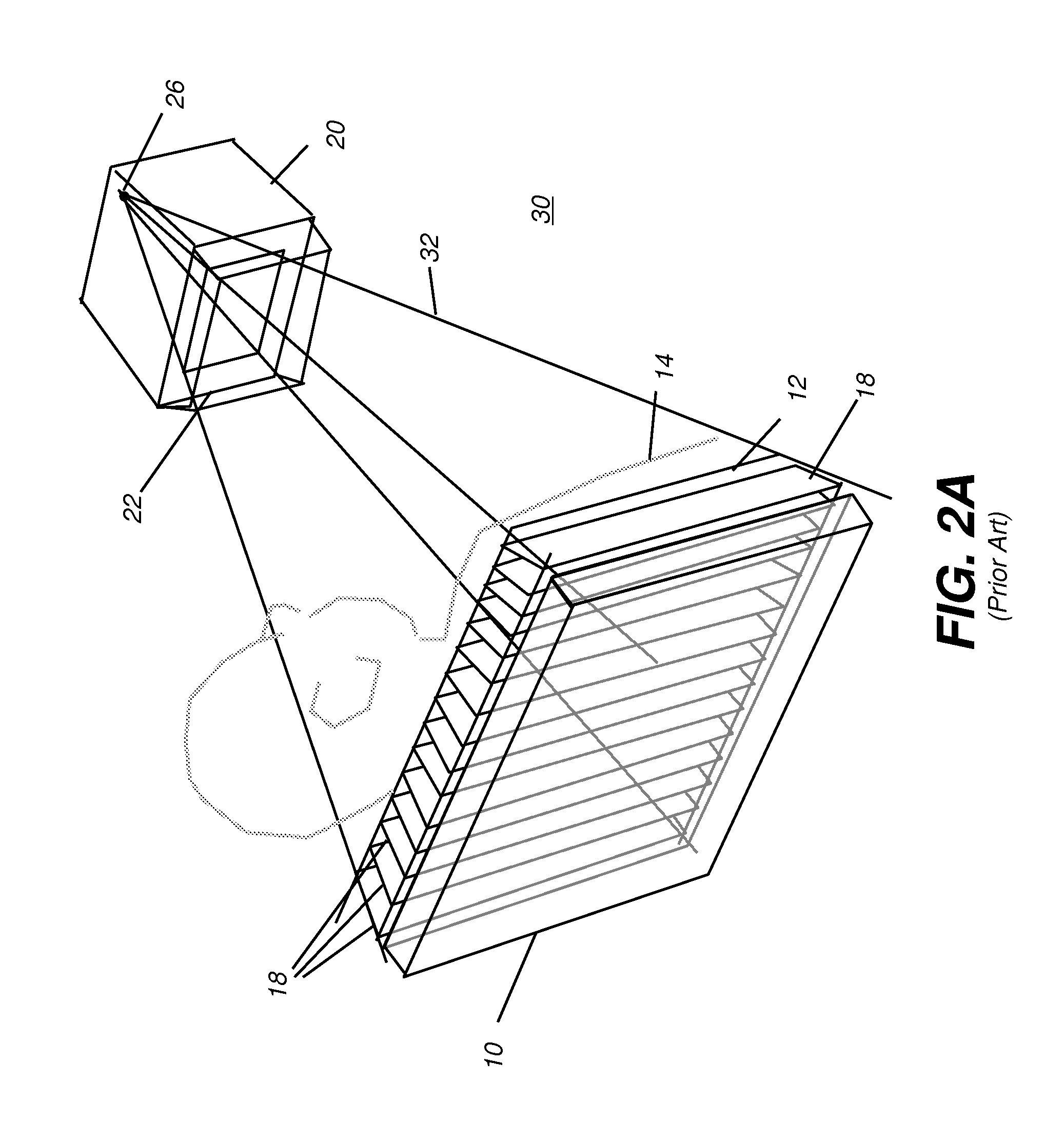
[0049]The perspective schematic view of FIG. 2A shows components of a radiographic imaging apparatus 30 in which a radiation source 20 emits a radiation beam 32 that is shaped by a collimator 22 and directed toward a patient 14. A receiver 10 positioned behin...


PUM


Abstract

A radiography system for obtaining a radiographic image of a subject, has a radiation source within an enclosure, the radiation source energizable to direct radiant energy along a radiation path toward an imaging receiver, wherein the radiation path is defined according to a collimator. A digital projector is coupled to the enclosure and is energizable to provide an illumination beam that outlines the defined radiation path.

Description

CROSS REFERENCE TO RELATED APPLICATION[0001]The present application is a Continuation-in-Part of U.S. Ser. No. 13 / 083,860 filed Apr. 11 2011 and entitled “TUBE ALIGNMENT FOR MOBILE RADIOGRAPHY SYSTEM” by Lalena et al., which, in turn, claims benefit of U.S. Provisional Application Ser. No. 61 / 323,476, filed 13 Apr. 2010, entitled “MOBILE UNIT HAVING TUBE ALIGNMENT SYSTEM,” by Lalena.[0002]The present application further claims priority to U.S. Provisional Application Serial No. 61 / 449,932, filed 7 Mar. 2011, entitled “GRAPHIC USER INTERFACE FOR MOBILE UNIT” by Stagnitto et al.FIELD OF THE INVENTION[0003]The invention relates generally to the field of radiographic imaging, and in particular to alignment apparatus for the x-ray source in a radiographic imaging system. More specifically, the invention relates to an apparatus and method for using a projector as an indicator of the area that lies in the path of the exposure beam.BACKGROUND OF THE INVENTION[0004]When an x-ray image is obt...

Claims


Application Information

Patent Timeline
Patent Type & Authority Applications(United States)
IPC IPC(8): A61B6/08
CPCA61B6/08A61B6/4208A61B6/4266A61B6/4405A61B6/542A61B6/4291A61B6/4241
Inventor LALENA, MICHAEL C.WANG, XIAOHUISTAGNITTO, JOSEPH E.
Owner CARESTREAM HEALTH INC
Why Eureka
Try Eureka