Hybrid particle, photoelectric conversion element, photosensitive body, and image forming apparatus
a photoelectric conversion element and hybrid particle technology, applied in the direction of radiofrequency controlled devices, instruments, electrographic processes, etc., can solve the problems of ineffective extraction of inability to realize original photoelectric conversion efficiency, and inability to effectively remove photoexcitation carriers from charge generation layers, etc., to achieve the suppression of recombination of photoexcited carriers, the effect of reducing the defect and void at the interface between the electron transport layer and the light absorption layer
- Summary
- Abstract
- Description
- Claims
- Application Information
AI Technical Summary
Benefits of technology
Problems solved by technology
Method used
Image

Examples
first embodiment
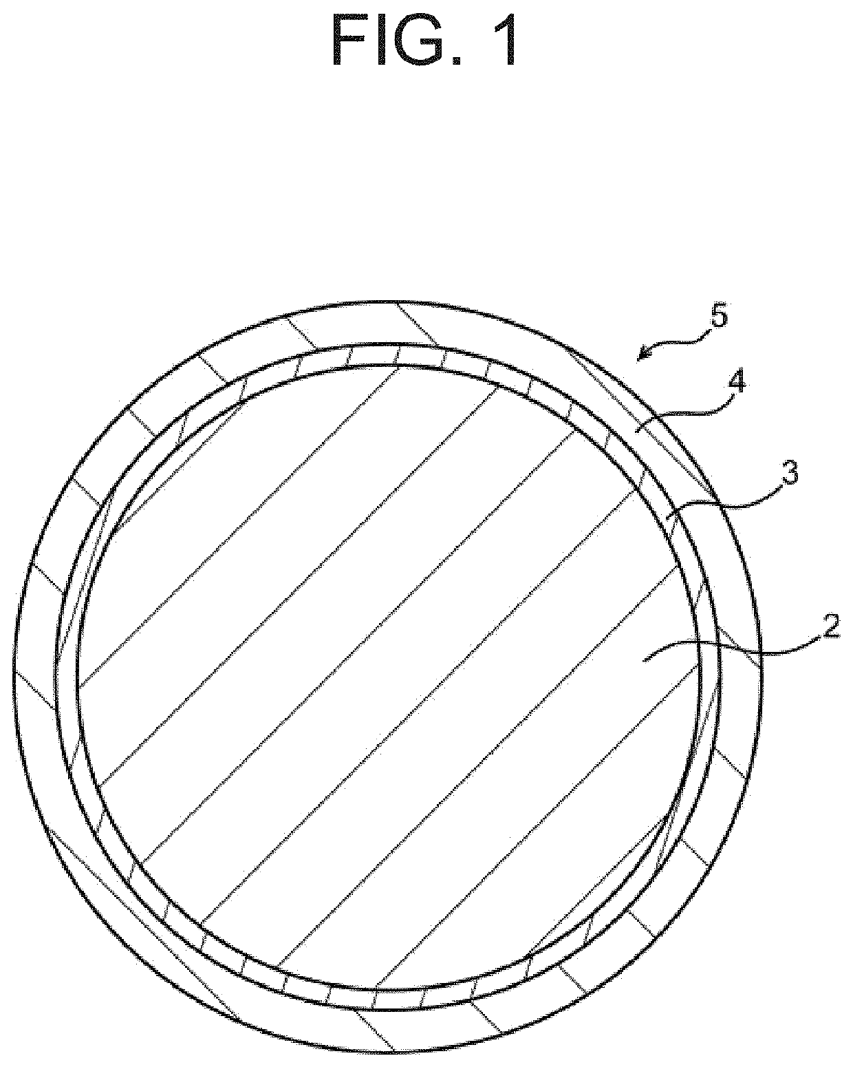
[0036]FIG. 1 is a schematic cross-sectional view of a hybrid particle according to the present embodiment.
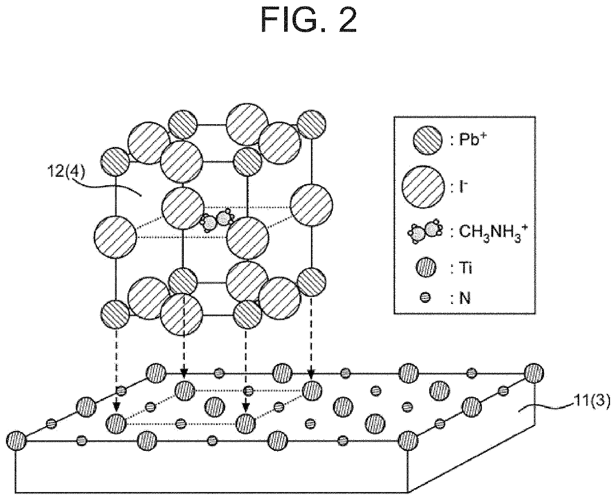
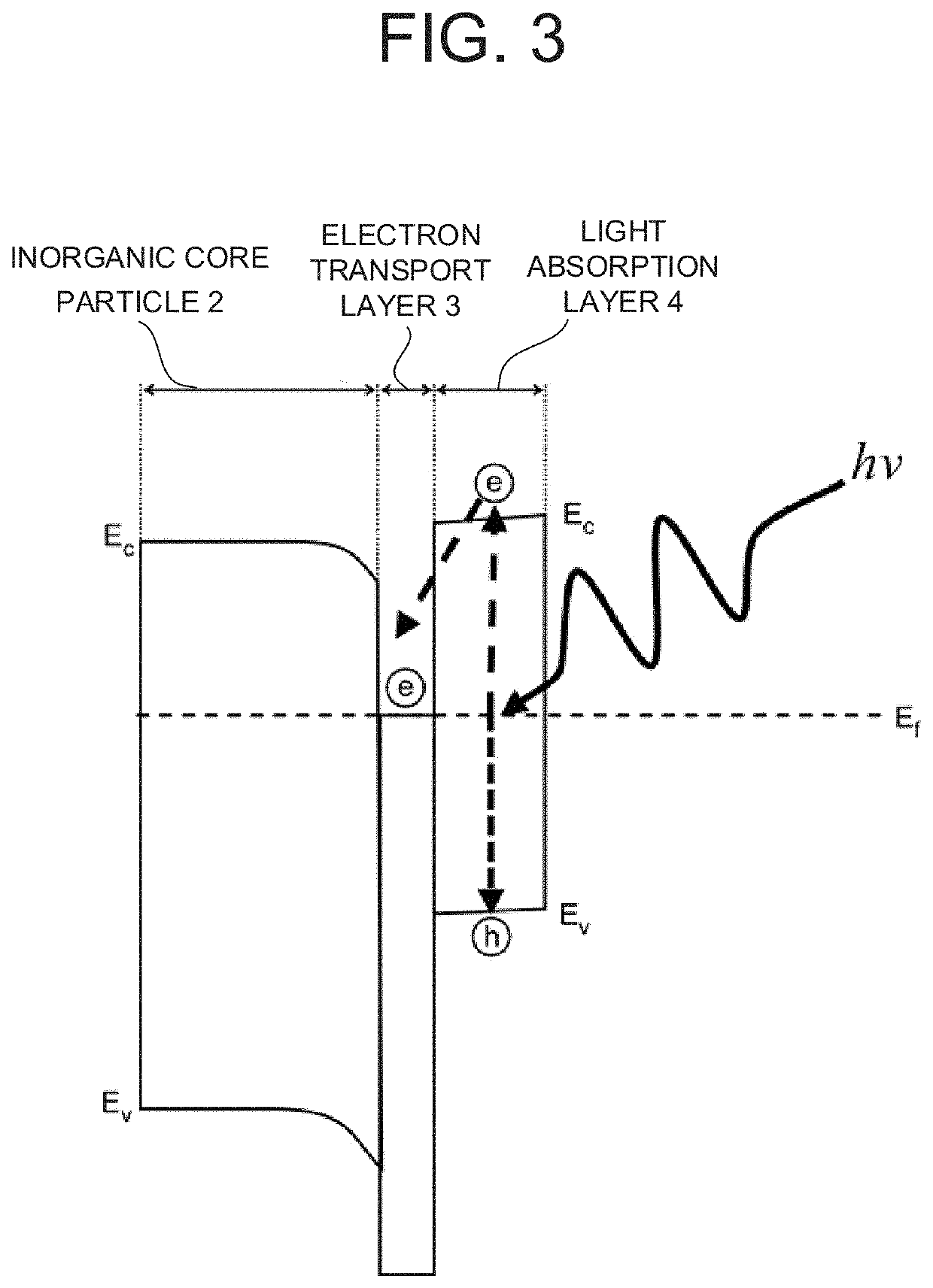
[0037]A hybrid particle 5 according to the present embodiment includes an inorganic core particle 2, an electron transport layer 3 covering a surface of the inorganic core particle 2, and a light absorption layer 4 covering the electron transport layer 3. The light absorption layer 4 contains a compound having an organic-inorganic hybrid perovskite crystal structure or a metal complex. The compound or the metal complex is grown in a crystalline form on a surface of the electron transport layer 3.
[0038]The hybrid particle 5 is a particle in which different materials are combined. The particle size of the hybrid particle 5 is, for example, 10 nm or more and 100 μm or less, and preferably 50 nm or more and 10 μm or less.
[0039]The inorganic core particle 2 is a particle made of an inorganic material, and is a particle serving as a base material of the hybrid particle 5. The particle...
second embodiment
[0064]In the hybrid particle 5 according to the first embodiment, the light absorption layer 4 contains a perovskite structure compound. However, in the hybrid particle 5 of the second embodiment, the light absorption layer 4 contains a metal complex as a dye instead of the perovskite structure compound. Other configurations are the same as those of the first embodiment.
[0065]A metal complex includes a metal or metal ion located at the center of the molecule, and ligands surrounding the metal or metal ion. A metal complex has highest occupied orbital HOMO and lowest unoccupied orbital LUMO. In a metal complex, light having an energy greater than the energy gap between HOMO and LUMO (the difference between the energy level of the HOMO and the energy level of the LUMO) is absorbed. As a result, an electron moves (transitions) from an orbital containing electrons to an empty orbital, which generates photoexcited carriers (an electron and a hole). The photoexcited electrons migrate to t...
third embodiment
[0079]The first and second embodiments described the hybrid particle 5. In the third embodiment, a photoelectric conversion element including the hybrid particle 5 of the first or second embodiment will be described. FIG. 9, FIG. 11, and FIGS. 12A, 12B, and 12C are cross-sectional views of the photoelectric conversion element of the present embodiment. FIG. 10, FIG. 13, FIG. 14, and FIG. 15 are energy band diagrams of the photoelectric conversion element according to the present embodiment.
[0080]The photoelectric conversion element 15 according to the present embodiment includes a first electrode 8, a charge separation layer 6 provided on the first electrode 8, and a second electrode 9 provided on the charge separation layer 6, wherein the charge separation layer 6 includes a hole transport layer 7 and a plurality of hybrid particles 5 of the first or second embodiment, and the plurality of hybrid particles 5 are covered by the hole transport layer 7.
[0081]The photoelectric conversi...
PUM
| Property | Measurement | Unit |
|---|---|---|
| particle size | aaaaa | aaaaa |
| particle size | aaaaa | aaaaa |
| particle size | aaaaa | aaaaa |
Abstract
Description
Claims
Application Information
 - R&D Engineer
- R&D Manager
- IP Professional
- Industry Leading Data Capabilities
- Powerful AI technology
- Patent DNA Extraction
Browse by: Latest US Patents, China's latest patents, Technical Efficacy Thesaurus, Application Domain, Technology Topic.
© 2024 PatSnap. All rights reserved.Legal|Privacy policy|Modern Slavery Act Transparency Statement|Sitemap