
Eureka
For R&D, Eureka makes reading and utilizing patents & technical documents easy.
Eureka AIR
Designed for self-driven R&D workflows. Generate viable solutions, solve complex R&D challenges, empower your innovation with AI.

Eureka Materials
Designed for material experts only. Revolutionize your material R&D, from search, analyze, to developing new materials.

TechResearch
Generate reliable direction feasibility study reports for your R&D in just a few steps.

TechSeek
Discover and master advanced knowledge NOW. Basics, ideas, possibilities, all at once.

TechMind
As an expert in R&D Theories, TechMind can generates customized viable solutions instantly.

TechRisk
Analyze your overall solution with one click, know your potential R&D risks in advance.

TechMonitor
Get weekly tech updates, stay abreast of the latest tech innovations and key insights.
Valve device
- Summary
- Abstract
- Description
- Claims
- Application Information
AI Technical Summary
Benefits of technology
Problems solved by technology
Method used
Image

Examples
first embodiment
Operation of First Embodiment
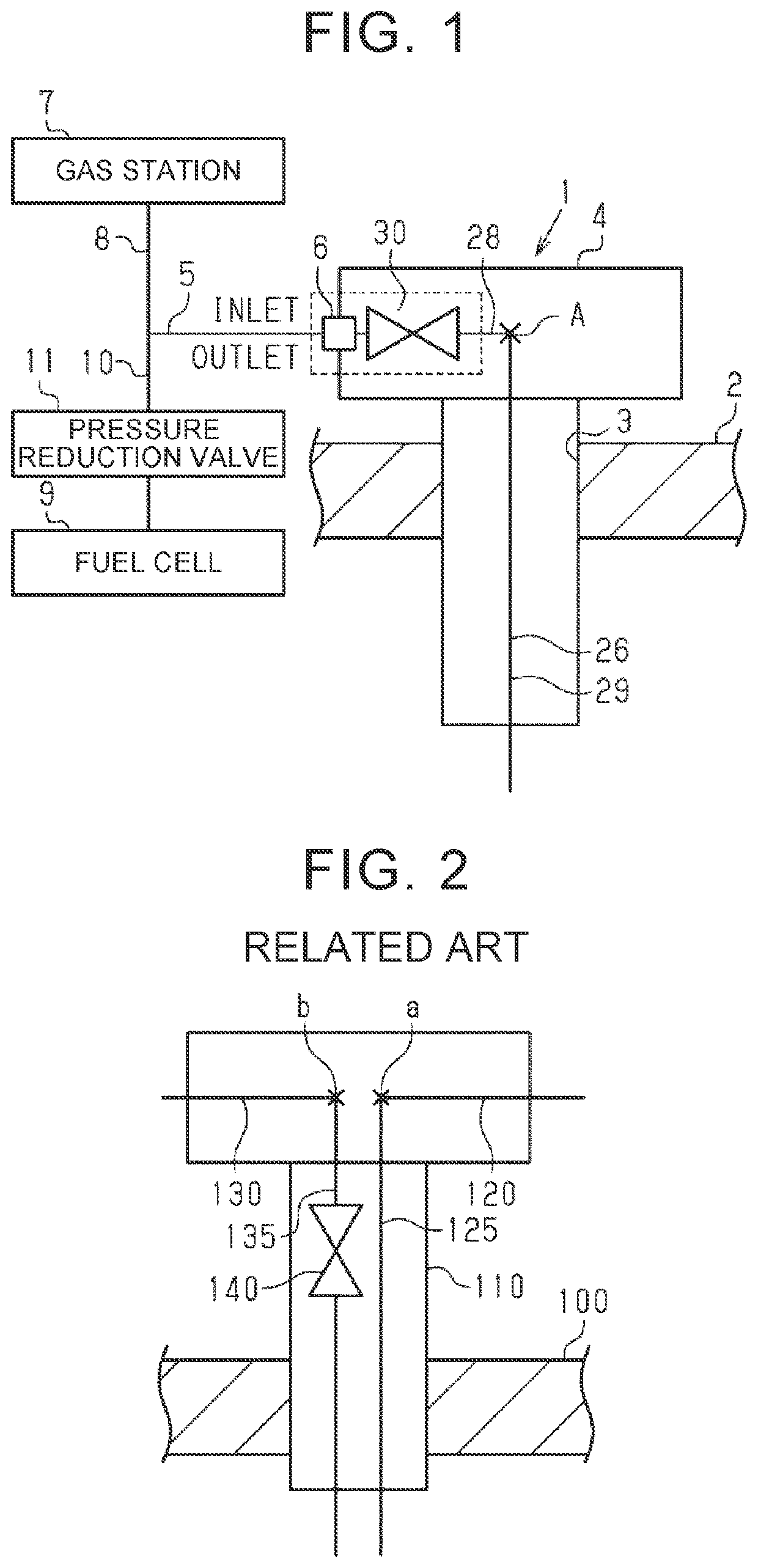
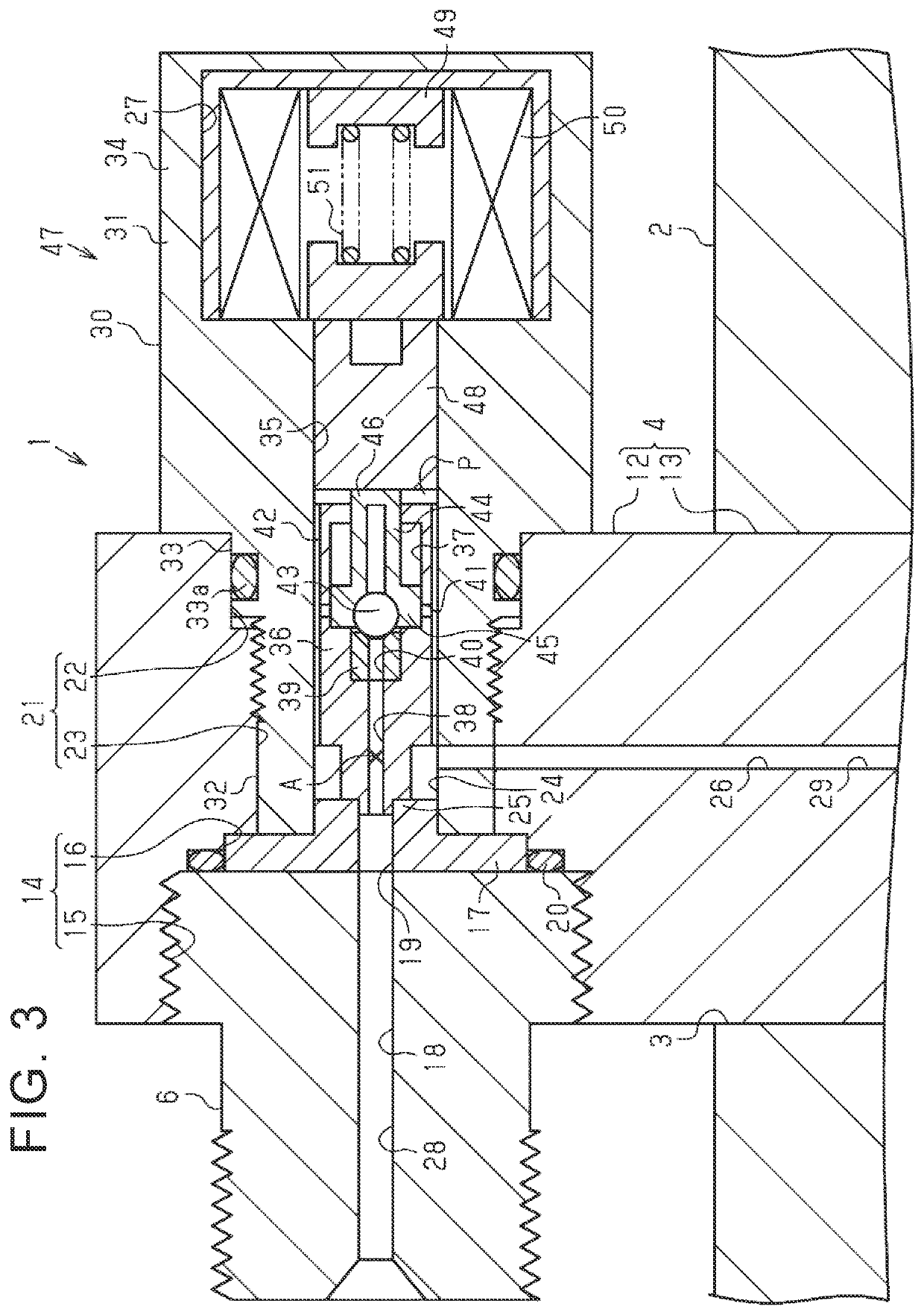
[0045]The operation of the valve device 1 configured as described above will be described with reference to FIG. 1 and FIGS. 3 to 5.
[0046]FIG. 3 shows a state where both the main valve 36 and the pilot valve 43 of the valve device 1 are closed. That is, with the urging force of the coil spring 51 pressing the plunger 48, the pilot valve 43 is closed and the main valve 36 is closed.
[0047]Here, reference sign P2 represents the pressure in the storage chamber of the tank 2, reference sign P3 represents the pressure in the space P surrounded by the end wall of the main valve 36 and the plunger 48, and reference sign P1 represents the pressure in the passage 18. In FIG. 3, P12 is established. In this state, the space P surrounded by the end wall of the main valve 36 and the plunger 48 communicates with the passage 26 via the communication grooves 42 and the valve chamber 24. Thus, P3=P2 (pressure in the space P=pressure in the storage chamber of the tank 2) i...
second embodiment
Operation of Second Embodiment
[0062]The operation of the valve device 1 configured as described above will be described. FIG. 6 shows a state in which the main valve 36 of the valve device 1 is closed. That is, the urging force of the coil spring 51 presses the plunger 48 to close the main valve 36.
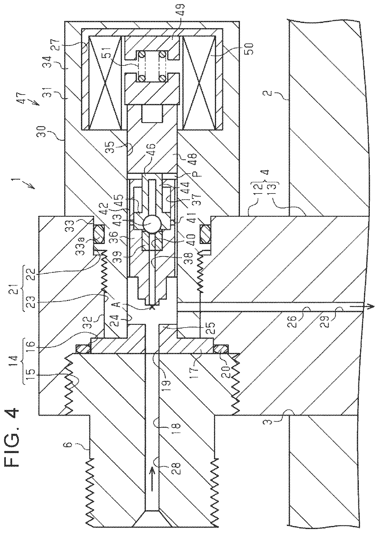
[0063]When the hydrogen gas is charged, as shown in FIG. 7, the hydrogen gas is supplied from the passage 18, and the pressure caused by the supply of the hydrogen gas opens the main valve 36 against the urging force of the coil spring 51. With the main valve 36 opened, the hydrogen gas is stored in the storage chamber of the tank 2 via the valve chamber 24 and the passage 26. When the charge of hydrogen gas is stopped, the main valve 36 is closed by the urging force of the coil spring 51.
[0064]When the hydrogen gas in the storage chamber of the tank 2 is discharged to the fuel cell 9, the electromagnetic coil 50 is excited. With this excitation, the plunger 48 moves the main valve 36 awa...
PUM
 Abstract
Description
Claims
Application Information
 - R&D Engineer
- R&D Manager
- IP Professional
- Industry Leading Data Capabilities
- Powerful AI technology
- Patent DNA Extraction
Browse by: Latest US Patents, China's latest patents, Technical Efficacy Thesaurus, Application Domain, Technology Topic, Popular Technical Reports.
© 2024 PatSnap. All rights reserved.Legal|Privacy policy|Modern Slavery Act Transparency Statement|Sitemap|About US| Contact US: help@patsnap.com