
Method and apparatus for mitigation of low frequency noise in radar systems

a radar system and low frequency noise technology, applied in the field of radar systems, to achieve the effect of suppressing the power of low frequency noise, improving the performance of the radar system, and improving the detection ability of small objects

Active Publication Date: 2020-09-17
UHNDER INC
View PDF7 Cites 11 Cited by
  • Summary
  • Abstract
  • Description
  • Claims
  • Application Information

AI Technical Summary

Benefits of technology

The present invention provides methods and a system for improving the performance of a radar system affected by low frequency noise. The invention redistributes signal power and filters out low frequency noise to improve the detection of small objects and accurate estimation of their distance, velocity, and position. The use of a low intermediate frequency (IF) reduces the bandwidth requirements for separating the signal power spectrum from the DC offset and flicker noise spectrum, allowing for digital processing. Choosing the IF frequency in both the receiver and transmitter provides an advantage in cost and radar system performance. The invention also helps in sharing the RF local oscillator (RFLO) between the transmitter and receiver.

Problems solved by technology

Such low frequency noise may include DC offset and / or flicker noise introduced by components of the radar system itself.

Method used


Image

  • Method and apparatus for mitigation of low frequency noise in radar systems
  • Method and apparatus for mitigation of low frequency noise in radar systems
  • Method and apparatus for mitigation of low frequency noise in radar systems

Examples


Embodiment Construction

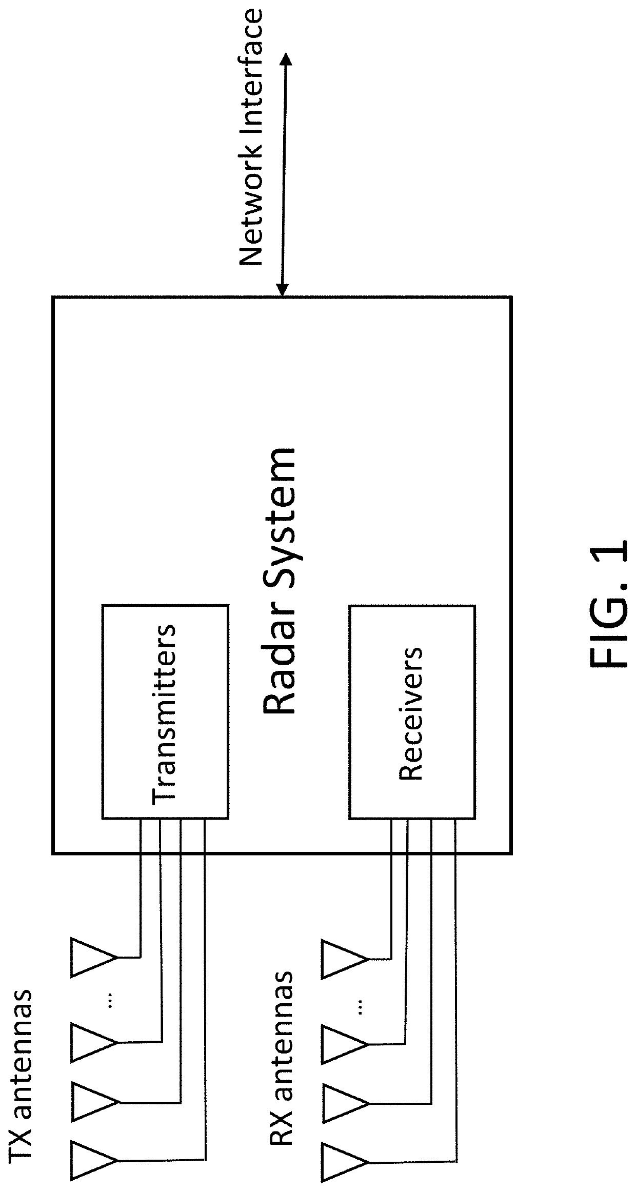
[0043]The present invention will now be described with reference to the accompanying figures, wherein numbered elements in the following written description correspond to like-numbered elements in the figures. Methods and systems of the present invention result in better performance from a radar system. An exemplary radar system utilizes one or more transmit (TX) antennas to transmit signals as illustrated in FIG. 1. These signals are reflected from objects (also known as targets) in the environment and received by one or more receive (RX) antennas of the radar system, also illustrated in FIG. 1. The radar system also has one or more interfaces to other systems. For example, the network interfaces may include Ethernet, USB, or in an automotive radar system may include CAN-FD and / or FlexRay. There may also be processing capability contained in the radar system apart from the transmitters and receivers.

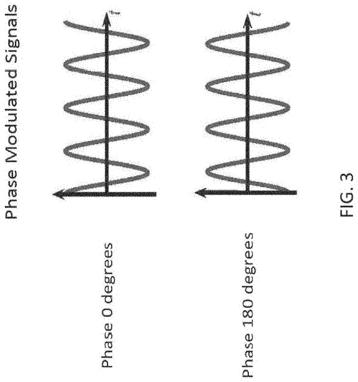
[0044]There are several types of signals used in different types of radar systems. ...


PUM


Abstract

A radar sensing system includes a transmitter and a receiver. The transmitter is configured to transmit a radio signal. The receiver is configured to receive radio signals that include the transmitted radio signal reflected from objects in the environment. The transmitter and receiver are configured to distribute the signal power over frequency so that it is separated from noise and impairments at DC and low frequencies as may be caused by some radar system components which introduce DC offsets and / or low frequency (e.g. flicker) noise.

Description

CROSS REFERENCE TO RELATED APPLICATIONS[0001]The present application claims the filing benefits of U.S. provisional application, Ser. No. 62 / 816,941, filed Mar. 12, 2019, which is hereby incorporated by reference herein in its entirety.FIELD OF THE INVENTION[0002]The present invention is directed to radar systems, and in particular to radar system transmitters and receivers.BACKGROUND OF THE INVENTION[0003]The use of radar to determine location and velocity of objects in an environment is important in a number of applications including, for example, automotive radar, industrial processes, and gesture detection. A radar system typically transmits radio signals and listens for the reflection of the radio signals from objects in the environment. By comparing the transmitted radio signals with the received radio signals, a radar system can determine the distance to an object, and the velocity of the object. Using multiple transmitters and / or receivers, or a movable transmitter or receiv...

Claims


Application Information

Patent Timeline
Patent Type & Authority Applications(United States)
IPC IPC(8): G01S7/35G01S13/32G01S13/36
CPCG01S13/36G01S2007/356G01S13/325G01S7/354G01S2007/358G01S13/931G01S13/584G01S7/4017G01S7/40G01S7/356G01S7/358
Inventor BEHRENS, RICHARDRUSH, FREDERICKMAHER, MONIERALI, MURTAZA
Owner UHNDER INC
Learn More