Control of an illuminator

Active Publication Date: 2020-09-17
AXIS
View PDF0 Cites 0 Cited by
  • Summary
  • Abstract
  • Description
  • Claims
  • Application Information

AI Technical Summary

Benefits of technology

[0006]Alleviating or eliminating one or more of the above-identified deficiencies in the art and disadv

Problems solved by technology

However, reducing the power to the illuminator may limit th

Method used


Image

  • Control of an illuminator
  • Control of an illuminator
  • Control of an illuminator

Examples


Embodiment Construction

[0032]The teachings will now be described more fully hereinafter with reference to the accompanying drawings, in which currently preferred embodiments of the invention are shown. This invention may, however, be embodied in many different forms and should not be construed as limited to the embodiments set forth herein; rather, these embodiments are provided for thoroughness and completeness, and to fully convey the scope to the skilled person.

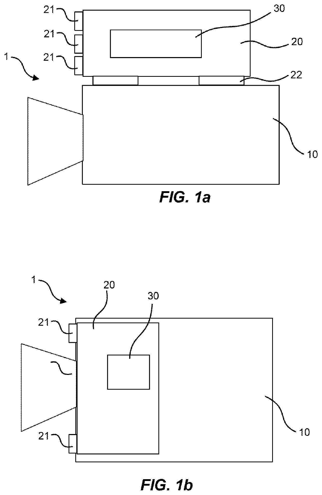
[0033]FIGS. 1a and 1b illustrate embodiments of a monitoring system 1. The monitoring system 1 comprises a monitoring camera 10 and an illuminator 20. The monitoring camera 10 is typically a digital video camera. The monitoring camera 10 is configured to monitor a scene. The illuminator 20 is configured to illuminate the scene monitored by the monitoring camera 10. The illuminator comprises one or more light sources 21. Each light source 21 is configured to emit light. The light emitted by the one or more light sources 21 forms a beam of illumin...


PUM


Abstract

A method for controlling an illuminator illuminating a scene monitored by a camera comprises determining whether an object of interest is present in the scene; upon at least one object of interest being determined to be present in the scene, setting a saturation threshold to a first value; or upon no object of interest being determined to be present in the scene, setting the saturation threshold to a second value being lower than the first value. The method further comprises identifying saturated pixels in an image of the scene captured by the camera; determining a ratio between a saturated area comprising the saturated pixels and a total area of the image; and upon the ratio being above the saturation threshold, decreasing a degree of illumination from the illuminator.

Description

TECHNICAL FIELD[0001]The present invention relates to controlling an illuminator illuminating a scene monitored by a camera. Also a controller configured to control the illuminator is presented.BACKGROUND[0002]When monitoring a scene using a camera, it is at times necessary to add light to the scene in order to enable capturing of images of sufficient quality. Illuminators may be integrated in the camera, or external to the camera. The illuminators may add visible light. However, since image sensors used in cameras are generally sensitive to infrared radiation (IR) or more specifically near infrared radiation (NIR), the illuminators may advantageously add IR instead of visible light. In this manner, a sufficient amount of light may be provided for image capture, while avoiding disturbing visible light. As discussed in the following, visible light and IR will both be referred to as “light”.[0003]The amount of light added to the scene needs to be controlled such that the scene is suff...

Claims


Application Information

Patent Timeline
IPC IPC(8): H04N5/235H04N5/225H04N5/21
CPCH04N5/21H04N5/2256H04N5/2354H04N23/74Y02B20/40H04N7/18H05B47/125H04N23/56H04N23/71
Inventor NAKATA, SHOTA
Owner AXIS
Why Eureka
Try Eureka