A device for converting thermal energy, a corresponding solar reactor and related plant

Inactive Publication Date: 2020-09-24
ARCHIMEDE SISTEMI IND S R L S
View PDF0 Cites 0 Cited by
  • Summary
  • Abstract
  • Description
  • Claims
  • Application Information

AI Technical Summary

Benefits of technology

[0028]A further object of the invention is to convert the thermal energy into a form of energy

Problems solved by technology

Current technology based upon plants for producing electrical energy from the thermodynamic solar source is struggli

Method used


Image

  • A device for converting thermal energy, a corresponding solar reactor and related plant
  • A device for converting thermal energy, a corresponding solar reactor and related plant
  • A device for converting thermal energy, a corresponding solar reactor and related plant

Examples


first embodiment

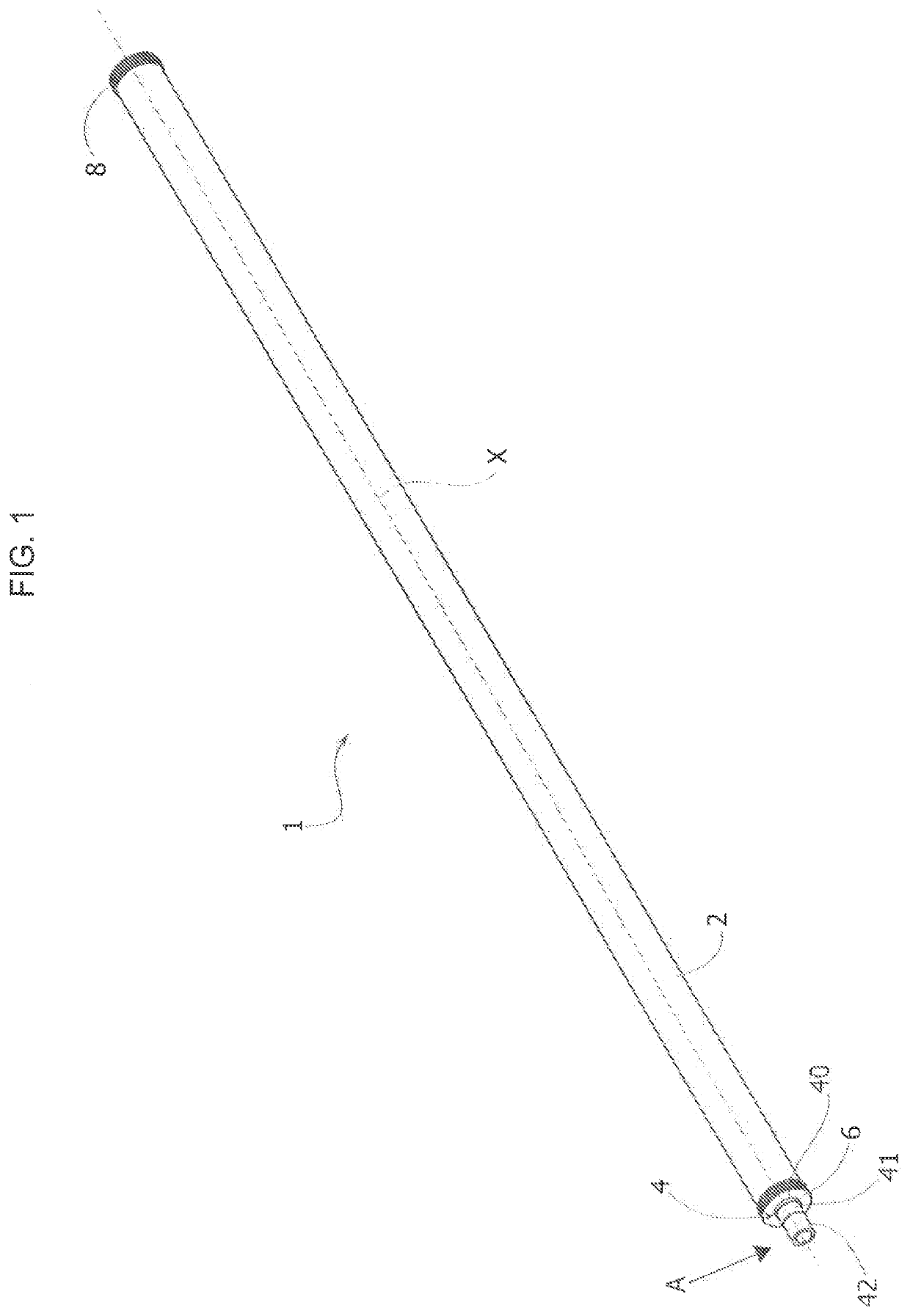
[0039]Reference number 1 in FIG. 1 designates as a whole a solar-energy converter device according to various embodiments of the invention, and here in particular according to a

[0040]The converter device 1 includes a shell 2 and a core 4, both developing axially along a longitudinal axis X and being coaxial to one another and to the axis X. Set at the ends of the converter 1 are a first end plate 6 and a second end plate 8, which delimit the converter and enclose in a fluid-tight way a volume comprised between the shell 2 and the core 4. Preferentially, the converter device 1 has an overall cylindrical shape so that both the shell 2 and the core 4 have an overall cylindrical shape. In this case, the volume comprised between the core 4 and the shell 2 is shaped like a cylindrical annulus. In the volume in question, vacuum is obtained.

[0041]In the preferred embodiments, the core 4 includes a tubular element 40, housed within which is a matrix 41, which in turn houses one or more flow ...

second embodiment

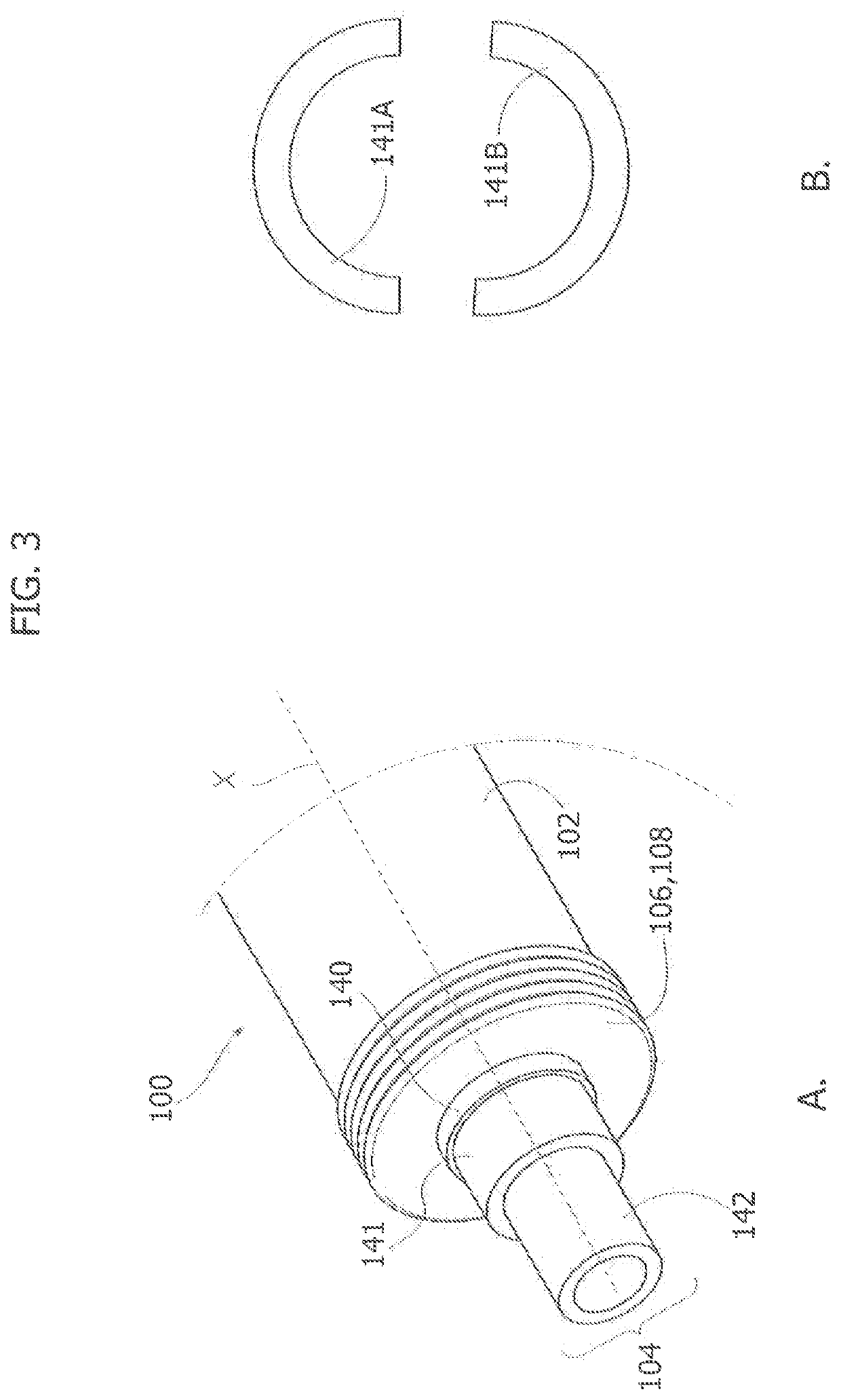
[0052]With reference to FIGS. 3A and 3B, the converter according to the invention is designated by the reference number 100. All the components that are functionally (and, where applicable, structurally) identical to the ones already described as regards the converter 1, are designated by the same reference numbers increased by 100. Hence, designated by 102 is the shell, by 104 is the core, by 106 and 108 are the first and second end plates, by 140 is the inner tubular element (where envisaged), by 141 is the matrix, by 141A and 141B are the half-sections, and by 142 is the flow conduit.

[0053]For this reason, the same structural and functional description already provided previously applies except where otherwise specified. In this regard, the embodiment in question differs from the converter 1 only in that now it is the matrix 141 that has a thick wall, whereas the flow conduit 142 has a thin wall.

third embodiment

[0054]With reference to FIGS. 4A and 4B, the converter according to the invention is designated by the reference number 200. All the components that are functionally (and, where applicable, structurally) identical to the ones already described as regards the converters 1, 100 are designated by the same reference numbers increased by 200. Hence, designated by 202 is the shell, by 204 is the core, by 206 and 208 are the first and second end plates, by 240 is the inner tubular element (where envisaged), by 241 is the matrix, and by 242 is the flow conduit (in this case, more than one).

[0055]For this reason, the same structural and functional description already provided previously applies, except where otherwise specified. In this regard, the embodiment in question differs from the converters 1, 100 only in that it includes a plurality of flow conduits 242, here in particular four arranged at the vertices of a square. The matrix 241 consequently includes four axial channels, each with ...


PUM


Abstract

Described is a solar-energy converter device including a shell and a core inside the shell, wherein the shell and the core develop axially along a longitudinal axis and include a volume therebetween. The core includes a thermally conductive matrix in a thermal exchange relationship with the volume, the matrix housing one or more flow conduits for a working fluid, the one or more flow conduits being in thermal exchange relationship with the matrix. Moreover, described is a corresponding solar reactor and a corresponding plant.

Description

FIELD OF THE INVENTION[0001]The present invention relates to energy-conversion plants and to the corresponding components, in particular to plants for exploiting and converting solar energy.PRIOR ART[0002]Current technology based upon plants for producing electrical energy from the thermodynamic solar source is struggling to take root, and consequently the unit production costs are far from being those typical of a mature technology. One of perhaps the most significant data available regards the fact that in roughly twenty years the production costs for these plants has dropped by barely ten times.[0003]Thermodynamic solar plants indirectly convert solar energy into electrical energy through two distinct energy-conversion steps.[0004]The first step consists in the conversion of solar energy into thermal energy stored in a thermovector fluid.[0005]The second step typically consists in conversion of the thermal energy into electrical energy by means of a conventional thermodynamic cyc...

Claims


Application Information

Patent Timeline
IPC IPC(8): F03G6/00F24S10/40F24S80/10F24S20/20F24S10/70F23G5/02F24S70/65C07C7/10
CPCF24S80/10F24S70/65F24S20/20C07C7/10F03G6/003F23G5/02F24S10/742F24S10/45Y02E10/44Y02E10/46
Inventor TUMMINELLI, GIANLUCATUZZOLINO, GAETANOGATTUSO, CALOGEROLUCE, ALESSANDRORIZZO, ROBERTOSANTORO, FABIO
Owner ARCHIMEDE SISTEMI IND S R L S
Why Eureka
Try Eureka