Circuit arrangement for the temperature-dependent actuation of a switching element

Active Publication Date: 2020-09-24
ROBERT BOSCH GMBH
View PDF0 Cites 0 Cited by
  • Summary
  • Abstract
  • Description
  • Claims
  • Application Information

AI Technical Summary

Benefits of technology

The patent describes a circuit arrangement with two switching elements that can be controlled separately. The first element controls a current path between the input and output connection, while the second element controls a further current path that can be connected or disconnected based on the control voltage. This allows for more efficient control of the first element and minimizes the impact of temperature changes on the overall resistance of the circuit. The circuit also includes a diode to prevent current flow through the second element when the first element is turned off. These technical effects make the circuit arrangement more suitable for precise and efficient control of current paths in various applications.

Problems solved by technology

Particularly in the case of high actuation currents and high clock frequencies, there is the danger of the inherent heating of the temperature-dependent resistor taking place faster than the heating of the semiconductor itself.
The resulting operation of the switching element at a comparatively insufficient series resistance can lead to harmful overvoltages and electromagnetic interference.

Method used


Image

  • Circuit arrangement for the temperature-dependent actuation of a switching element
  • Circuit arrangement for the temperature-dependent actuation of a switching element
  • Circuit arrangement for the temperature-dependent actuation of a switching element

Examples


Embodiment Construction

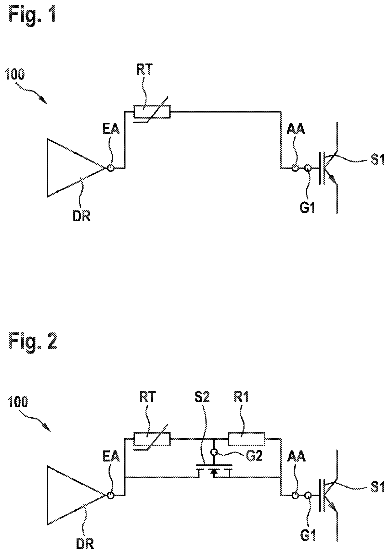
[0033]FIG. 1 shows a circuit arrangement 100, comprising an input connection EA, an output connection AA and a temperature-dependent component RT. A temperature-dependent resistor is illustrated as the temperature-dependent component RT, for example, which is arranged between the input connection EA and the output connection AA. The circuit arrangement serves for temperature-dependent actuation of a first switching element S1, the control connection G1 of which can be connected to the output connection AA. The input connection EA of the circuit arrangement 100 can be connected to the output of a driver circuit DR for receiving an input potential generated by the driver circuit DR. To reduce the effective total series resistance of the circuit arrangement 100 in the event of increasing temperatures, one solution is to use a resistor having a negative temperature coefficient (NTC) as the temperature-dependent resistor RT. In this configuration, the effective total series resistance of...


PUM


Abstract

The invention relates to a circuit arrangement (100) for the temperature-dependent actuation of a first switching element (S1), comprising an input terminal (EA) for accepting an input potential, an output terminal (AA) for transferring an output potential to a first control terminal (G1) of the first switching element (S1), and a temperature-dependent component (RT) which is connected between the input terminal (EA) and the output terminal (AA).

Description

BACKGROUND OF THE INVENTION[0001]The invention relates to a circuit arrangement for the temperature-dependent actuation of a first switching element. The invention further relates to a circuit module, an inverter and the use of the circuit arrangement.[0002]Switching elements, in particular power semiconductor switches, such as bipolar transistors, IGBTs, MOSFETs, are actuated using a driver circuit. In this case, in order to close the switching element, a prescribable, fixed voltage potential is applied to the control connection of the semiconductor, to the gate. The switching speed of the switching element can be set by a series resistor, which is arranged between the actuation circuit and the control connection of the semiconductor. The higher the series resistance, the slower and less prone to losses the switching process. However, the temperature-dependent switching behavior of a semiconductor cannot be taken into account by means of said series resistor. It is known that the s...

Claims


Application Information

Patent Timeline
IPC IPC(8): H03K17/74H03K17/16
CPCH03K17/74H03K17/163H02P27/06
Inventor SINN, PETERBARTSCH, TIMO
Owner ROBERT BOSCH GMBH
Why Eureka
Try Eureka