

Terminal connection structure and display device
A terminal connection and structure technology, applied in the direction of connection, identification device, fixed connection, etc., can solve the problems of unstable connection state, connection reliability problems, fluidity, uneven filling amount and other problems of different-directional conductive tapes, so as to ensure Connection reliability, high connection reliability, effect of reducing effective resistance
- Summary
- Abstract
- Description
- Claims
- Application Information
AI Technical Summary
Problems solved by technology
Method used
Image

Examples
Embodiment approach 1
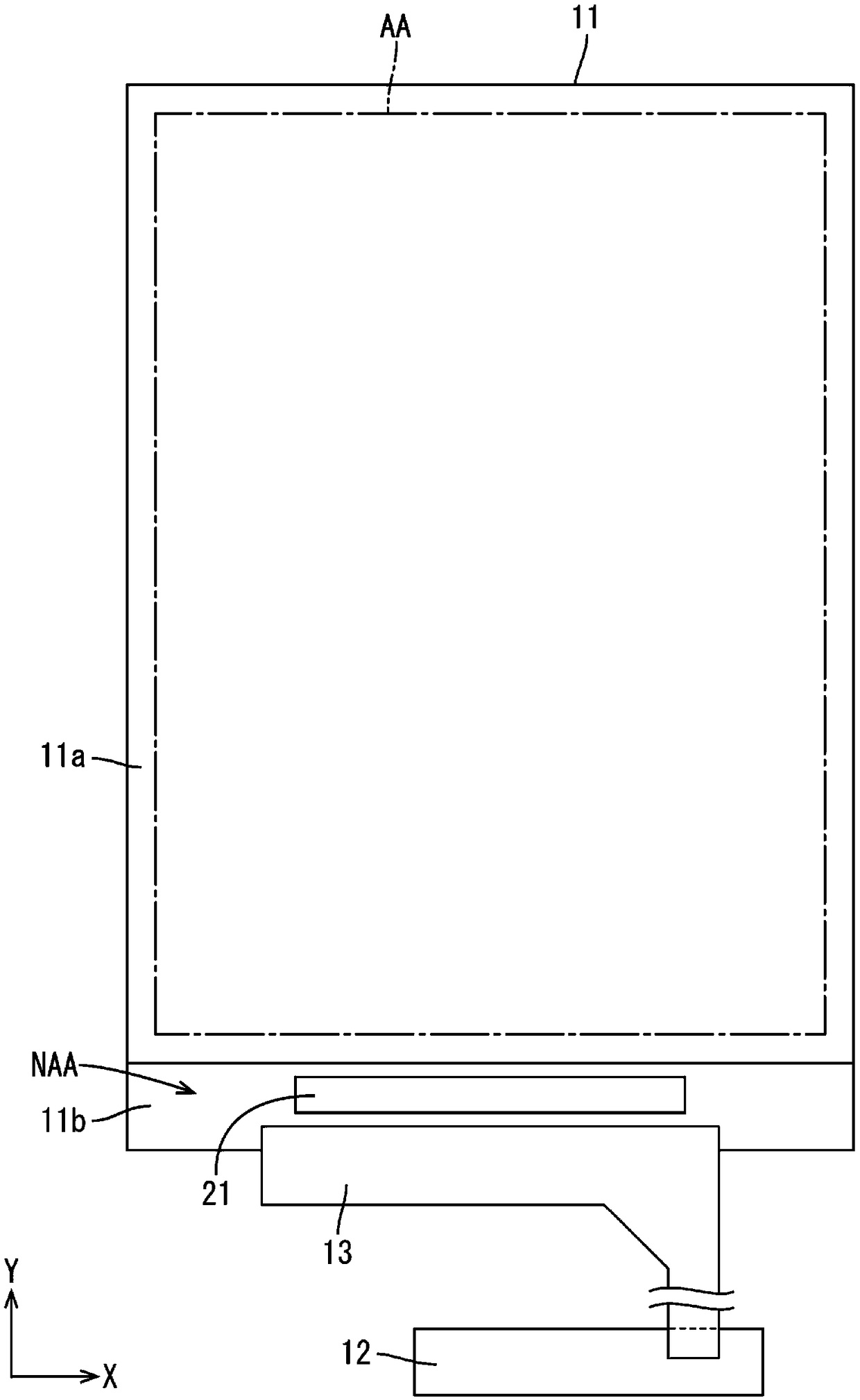
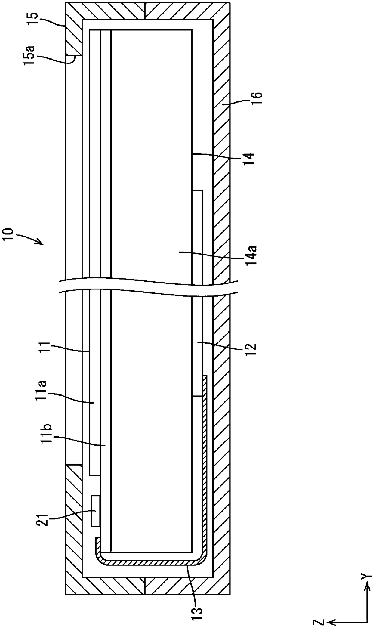
[0049] use Figure 1 to Figure 11 Embodiment 1 of the present invention will be described. In the present embodiment, the terminal connection structure between the liquid crystal panel 11 and the flexible substrate 13 included in the liquid crystal display device 10 is shown as an example. In addition, a part of each drawing shows an X-axis, a Y-axis, and a Z-axis, and it draws so that each axis direction may become the direction shown in each drawing. In addition, for the up-down direction, take figure 2 etc. as a reference, and the upper side in the same figure as the front side and the lower side in the same figure as the back side.
[0050] Such as figure 1 as well as figure 2 As shown, the liquid crystal display device 10 includes: a liquid crystal panel (display panel) 11; a driver (panel drive unit, mounting part) 21, which drives the liquid crystal panel 11; a control circuit board (external signal supply source) 12, which faces each other from the outside. Vari...
Embodiment approach 2
[0077] use Figure 12 Embodiment 2 of the present invention will be described. In the second embodiment, an embodiment in which the arrangement of the terminal connection portion 132 is changed is shown. In addition, repeated descriptions of the same configurations, actions, and effects as those of the first embodiment will be omitted.
[0078] Such as Figure 12 As shown, the terminal connection portion 132 of this embodiment connects the front end portion 130a2 of the adjacent divided large flexible substrate side terminal 130a in the large flexible substrate side terminal portion 130, which is closer to the base end than the front end portion 130a3 (closer to the base end). Signal supply source, close to the upstream) part of the way to set. The front end portion 130a3 of the front end portion 130a2 of each divided large flexible substrate side terminal 130a has almost the same width as the base end portion 130a1, and is a non-expanded portion. That is, the front end si...
Embodiment approach 3
[0081] use Figure 13 Embodiment 3 of the present invention will be described. In this third embodiment, an embodiment in which the shape of the front-end side portion 232a2 of the divided large flexible board side terminal 230a is changed from the first embodiment described above is shown. In addition, repeated descriptions of the same configurations, actions, and effects as those of the first embodiment will be omitted.
[0082] Such as Figure 13 As shown, in the large flexible substrate side terminal portion 230 of this embodiment, the width of the front end portion 230a2 of each divided large flexible substrate side terminal 230a becomes wider from the base end side to the front end side. Specifically, among the three divided large flexible substrate side terminals 230a constituting the large flexible substrate side terminal portion 230, the front end side portions 230a2 of a pair of divided large flexible substrate side terminals 230a located at both ends in the arrang...
PUM
| Property | Measurement | Unit |
|---|---|---|
| thickness | aaaaa | aaaaa |
| thickness | aaaaa | aaaaa |
Abstract
Description
Claims
Application Information