

Radiography apparatus, radiography apparatus operation method, and radiography apparatus operation program
- Summary
- Abstract
- Description
- Claims
- Application Information
AI Technical Summary
Benefits of technology
Problems solved by technology
Method used
Image

Examples
first embodiment
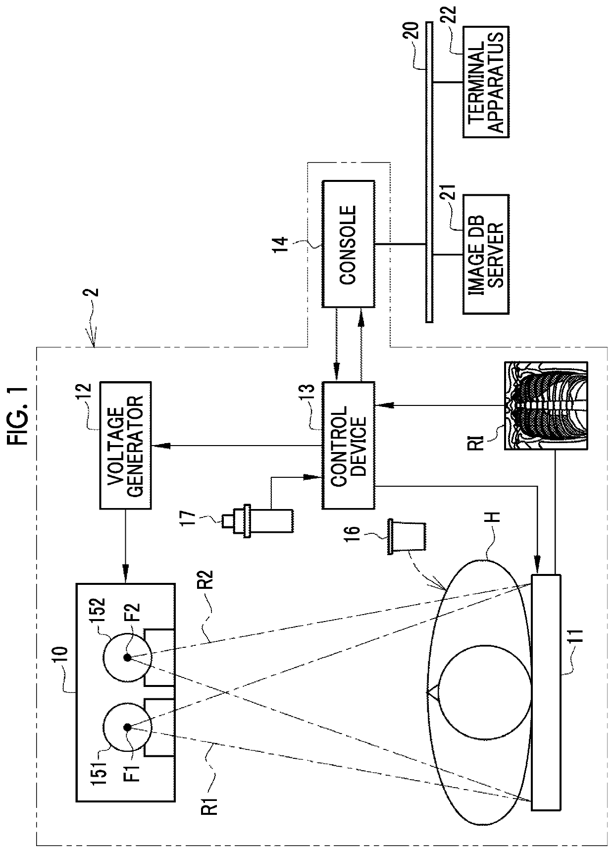
[0055]In FIG. 1, a radiography apparatus 2 comprises a radiation source 10, a radiation detector 11, a voltage generator 12, a control device 13, and a console 14. The radiation source 10, the radiation detector 11, the voltage generator 12, and the control device 13 are provided in, for example, a radiography room of a medical facility. The console 14 is provided in, for example, a control room adjacent to the radiography room. The radiography apparatus 2 is operated by an operator such as a radiology technician.
[0056]The radiation source 10 includes a first radiation tube 151 and a second radiation tube 152. The first radiation tube 151 generates first radiation R1 from a first focus F1. The second radiation tube 152 generates second radiation R2 from a second focus F2. Hereinafter, in some cases, the first radiation tube 151 and the second radiation tube 152 are collectively referred to as a “radiation tube 15”. Similarly, in some cases, the first focus F1 and the second focus F2...
second embodiment
[0129]In a Second Embodiment Illustrated in FIGS. 20 to 22, an Operation Unit is Provided which outputs the request signal RS to the receiving unit 77 in response to an operation command from the operator.
[0130]In FIG. 20, an irradiation switch 90 is connected to the control device 13 and includes a first switch SW1, a second switch SW2, and a third switch SW3 that are manually operated by the operator. The first switch SW1 and the second switch SW2 are two-stage push switches. In a case in which the first switch SW1 is pressed by the operator, the irradiation switch 90 outputs a signal for directing the radiation source 10 to perform a warm-up operation to the control device 13. In a case in which the second switch SW2 is pressed by the operator, the irradiation switch 90 outputs a signal for starting the moving image capture mode to the control device 13. In a case in which the third switch SW3 is pressed by the operator, the irradiation switch 90 outputs the request signal RS to ...
third embodiment
[0136]In a third embodiment illustrated in FIGS. 23 and 24, the average value of the generation intervals of the ES image ESI is greater longer than the frame interval FI.
[0137]FIG. 23 illustrates an example in which the generation interval of the ES image ESI is 2FI (about 0.07 seconds which is 15 frames / second in frame rate) which is twice the frame interval FI. This configuration in which the average value of the generation intervals of the ES image ESI is greater than the frame interval FI makes is possible to further reduce the load on the process of generating the ES image ESI.
[0138]The generation interval of the ES image ESI is not limited to the exemplified 2FI. The generation interval of the ES image ESI may be, for example, 1.5FI, 3FI, or 4FI. Further, as illustrated in FIG. 24, the case in which the ES image ESI is generated at the frame interval FI and the case in which the ES image ESI is generated at an interval longer (here, 2FI is exemplified) than the frame interval...
PUM
 Abstract
Description
Claims
Application Information