
System and Method for Scheduling Electric Generators using Decision Diagrams

a decision diagram and electric generator technology, applied in adaptive control, process and machine control, instruments, etc., can solve the problems of difficult combinatorial optimization task of ucp and meet the cost of electrical energy production, so as to reduce computational load, improve computer functionality, and reduce computing time. enormous

Active Publication Date: 2020-10-01
MITSUBISHI ELECTRIC RES LAB INC
View PDF0 Cites 3 Cited by
  • Summary
  • Abstract
  • Description
  • Claims
  • Application Information

AI Technical Summary

Benefits of technology

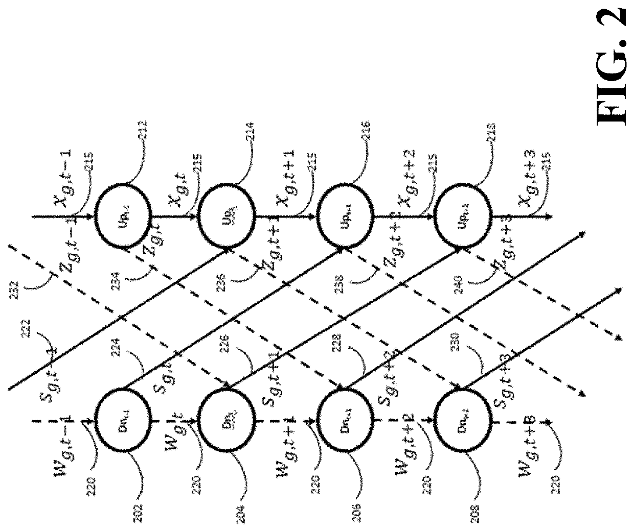
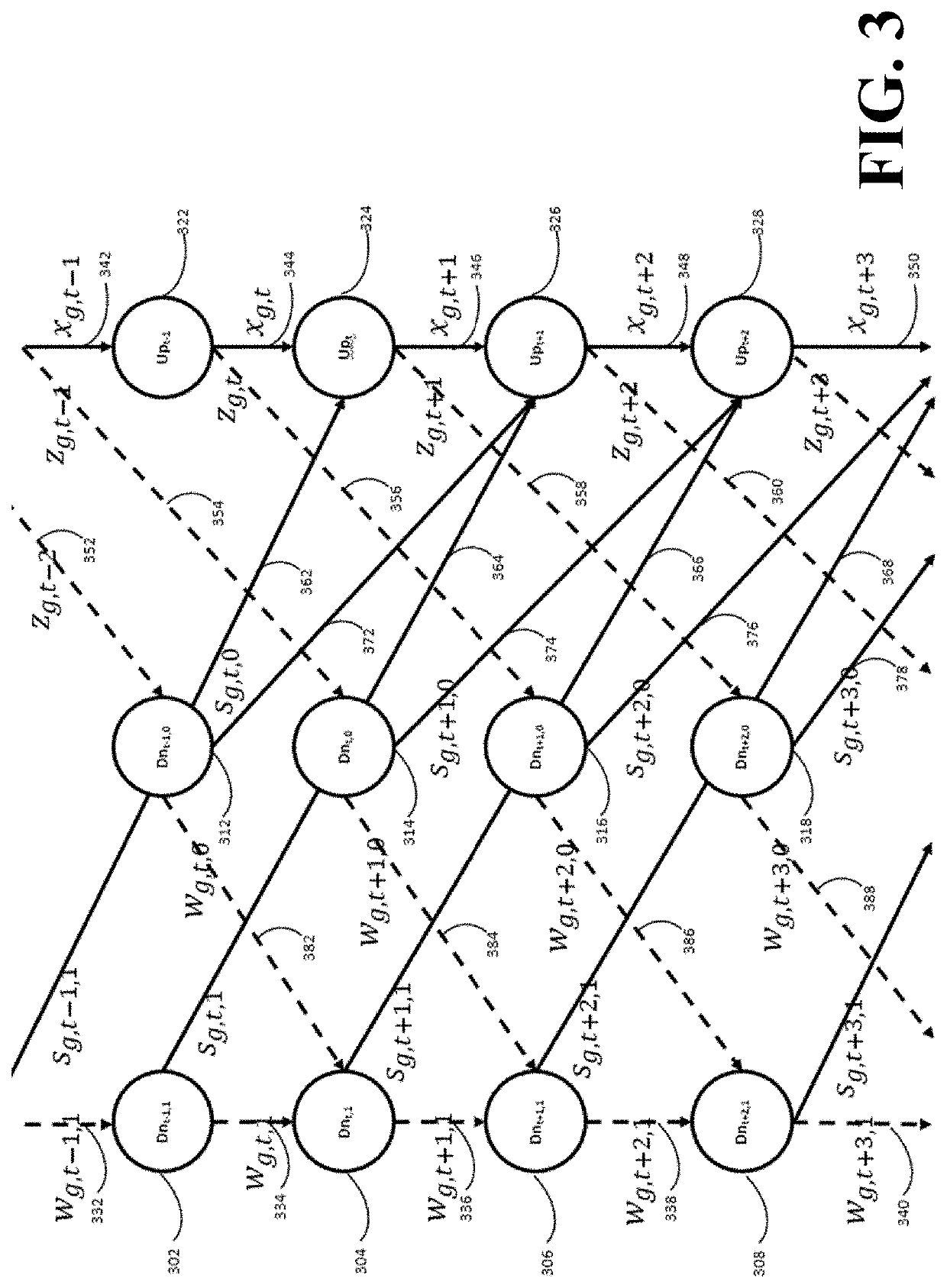
The present invention provides a new way to represent the space of possible operations of a generator using decision diagrams. This representation is used to formulate a network flow, which leads to improved computational performance. The invention also allows for a tight representation of the feasible operations of the generators, reducing computing time and improving computer function. Additionally, the invention presents a scenario-based two-stage mixed integer stochastic programming formulation that allows for a tight representation of the feasible operations of the generators while including uncertainty in the power demand.

Problems solved by technology

Generators are subject to constraints such as stable operating level, rate of ramping up or down, and the amount of time the generator is ON or OFF, which makes the UCP a difficult combinatorial optimization task, which arises when the operation of N individual generators is scheduled over T time steps, such that the total cost of producing electrical energy that meets the target power demand is minimized, while simultaneously observing the operational constraints of individual generators.

Method used


Image

  • System and Method for Scheduling Electric Generators using Decision Diagrams
  • System and Method for Scheduling Electric Generators using Decision Diagrams
  • System and Method for Scheduling Electric Generators using Decision Diagrams

Examples


Embodiment Construction

[0027]Various embodiments of the present invention are described hereafter with reference to the figures. It would be noted that the figures are not drawn to scale elements of similar structures or functions are represented by like reference numerals throughout the figures. It should be also noted that the figures are only intended to facilitate the description of specific embodiments of the invention. They are not intended as an exhaustive description of the invention or as a limitation on the scope of the invention. In addition, an aspect described in conjunction with a particular embodiment of the invention is not necessarily limited to that embodiment and can be practiced in any other embodiments of the invention.

[0028]The above-described embodiments of the present invention can be implemented in any of numerous ways. For example, the embodiments may be implemented using hardware, software or a combination thereof. When implemented in software, the software code can be executed ...


PUM


Abstract

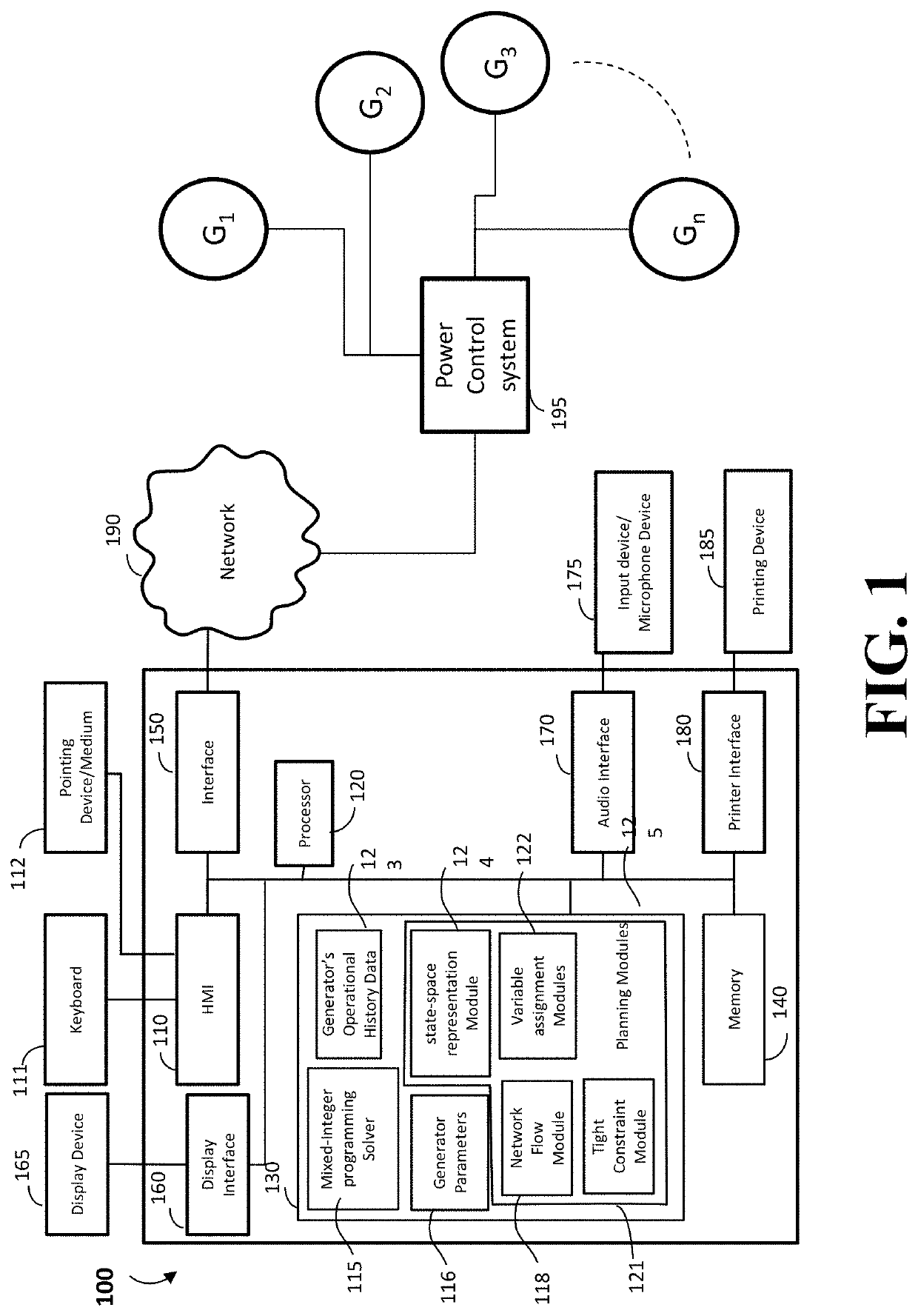
A power generation planning system for controlling on / off sequence of generators according to operational parameters includes an interface to receive the operational parameters including a power demand, state-data of the generators and operational histories of the generators from a power control system, a memory to store an objective function, a mixed-integer programming solver, generator parameters of each the generators and planning modules including a state-space representation module, a variable assignment module, a network flow module and a tight constraint module, a processor to perform the planning modules based on the operational parameters received by the interface. The processor is configured to construct decision diagrams for each of the generators by using the state-space representation module, generate arc-variables representing state-transformations of the generators by assigning binary variables to arcs of the decision, generate network flow constraints to represent feasible operations of each of the generators, generate tight constraints of each of the generators by using the tight constraint module and formulate a mixed-integer problem, solve the mixed-integer problem, by using the mixed-integer programming solver, based on the states-data of the generators, the network flow constraints and the tight constraints, and transmit on / off sequence data of each of the generators obtained from the solved mixed-integer problem to a power control system via the interface.

Description

FIELD OF THE INVENTION[0001]The present invention relates generally to System and method for scheduling electric generators, in particular, generating System and method for scheduling electric generators using decision diagrams.BACKGROUND & PRIOR ART[0002]The UCP involves determining schedules for generators so as to meet a target power demand. As used herein, a schedule specifies for each time instant in a horizon of T time steps—Boolean variables that indicate whether generators should be OFF or ON for a particular time step and continuous variables indicating the power to be produced and the maximum power that can be produced at that time. Generators typically include nuclear, thermal, and renewable power sources. Generators are subject to constraints such as stable operating level, rate of ramping up or down, and the amount of time the generator is ON or OFF, which makes the UCP a difficult combinatorial optimization task, which arises when the operation of N individual generato...

Claims


Application Information

Patent Timeline
Patent Type & Authority Applications(United States)
IPC IPC(8): G05B13/04H02J3/40G06F17/11
CPCG06F17/11H02J3/40G05B13/042H02J3/466H02J2203/20H02J2203/10Y04S40/20Y02E60/00
Inventor RAGHUNATHAN, ARVINDBERGMAN, DAVIDHASHIMOTO, HIROYUKI
Owner MITSUBISHI ELECTRIC RES LAB INC
Learn More