Metal sheet forming method, intermediate shape design method, metal sheet forming die, computer program, and recording medium

Active Publication Date: 2020-10-01
NIPPON STEEL CORP
View PDF0 Cites 0 Cited by
  • Summary
  • Abstract
  • Description
  • Claims
  • Application Information

AI Technical Summary

Benefits of technology

The patent describes a method for correcting element data to reduce differences in shape between elements in two sets of data. This method can be used, for example, to create a more accurate and precise model of a structure using computer simulations. The result is a more accurate and reliable model that can help with various applications such as engineering design and manufacturing.

Problems solved by technology

A reduction in sheet thickness is not necessarily uniform across portions deformed by pressing in press-forming a metal sheet.
In particular with high tensile strength steel, cracking occurs even when there is a slight reduction in sheet thickness.
However, in the method of Japanese Patent No. 4879588, there are limitations to the radius of curvature of the ridge line portion and to the tensile strength of the metal sheet (metal sheet prior to forming) of a blank, and this is an issue in that is imposes limitations on the shape of press-formed components.
However, the method described in JP-A No. 2007-326112 is a method suited to press-forming cylindrical containers, and application to shapes other than cylindrical containers is not considered.
The method disclosed in JP-A No. 2007-326112 forms a formed article using a single pressing process and so the shape of the die is complicated.
Moreover, the regions over which strain is distributed are limited to a punch shoulder and a vertical wall portion, and so the issues of necking and cracking that accompany sheet thickness reduction are not conclusively resolved.

Method used


Image

  • Metal sheet forming method, intermediate shape design method, metal sheet forming die, computer program, and recording medium
  • Metal sheet forming method, intermediate shape design method, metal sheet forming die, computer program, and recording medium
  • Metal sheet forming method, intermediate shape design method, metal sheet forming die, computer program, and recording medium

Examples


first exemplary embodiment

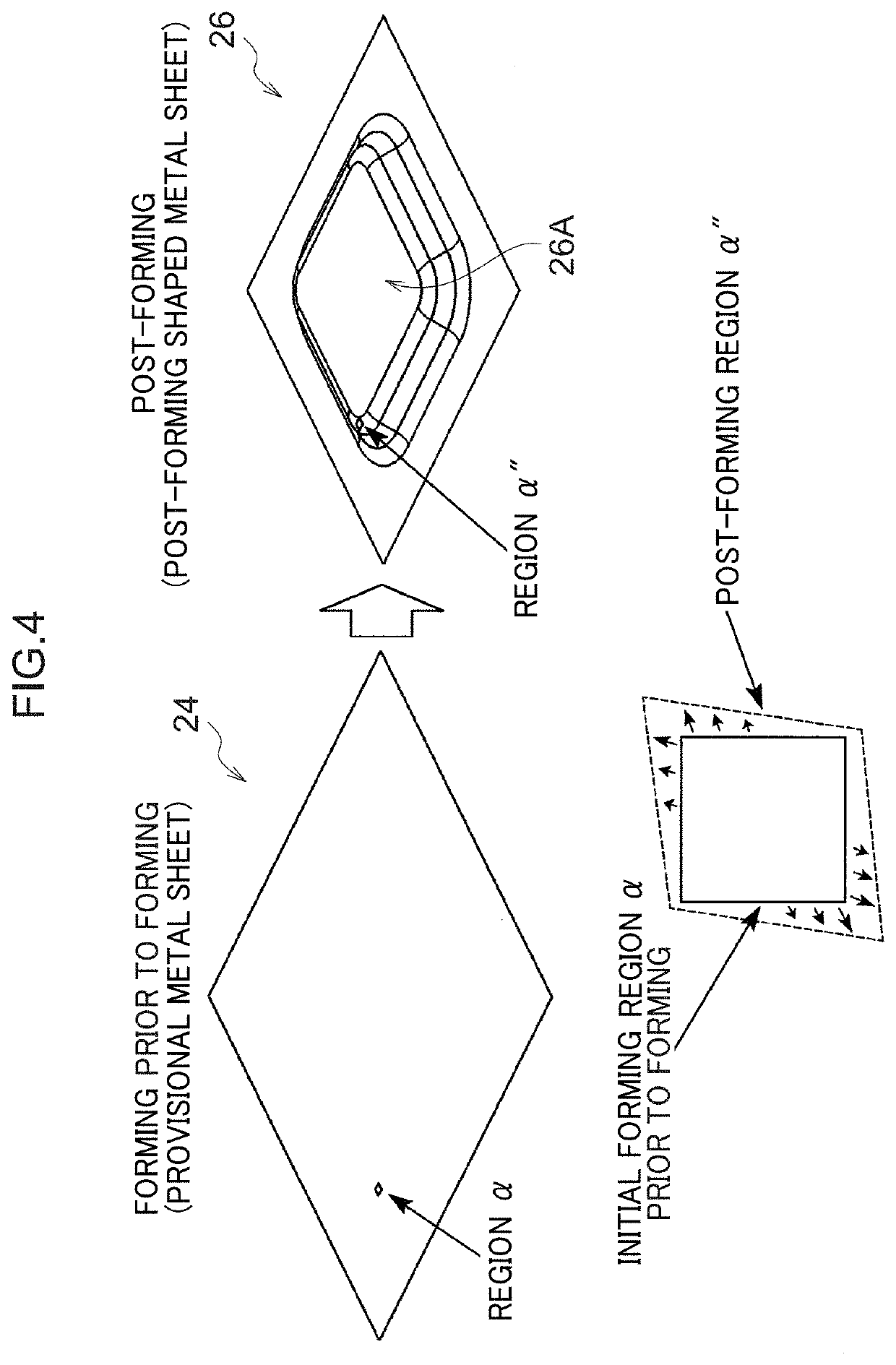
[0272]As illustrated by the flowchart in FIG. 6, a method of forming a metal sheet of a first exemplary embodiment is a method in which, when press-forming a metal sheet (90) to form a target shape, the metal sheet (90) is formed (91) into an intermediate shape that is different from the target shape, and a metal sheet formed into the intermediate shape (92) is then formed into the target shape to obtain a formed article (94). When this is performed, a shape obtained by following the procedure below is adopted as the intermediate shape. Namely, element data (D) for the hypothetical metal sheet 25 prior to forming is derived. A deformed shape is then adopted that has been deformed by imparting a strain to some elements in the element data (D) that is a strain required to deform each of these elements to the shape of each of the topologically corresponding elements in the element data (B) for the post-forming shaped metal sheet 26, while either imparting a strain to the remaining elem...

second exemplary embodiment

[0335]Explanation follows regarding a second exemplary embodiment.

[0336]Although in the first exemplary embodiment explanation has been given regarding an example in which a metal sheet blank is formed into the intermediate shape, and the intermediate shape is then formed into the target shape, the present invention is not limited to a single intermediate shape, and a blank may be formed into a target shape via plural intermediate shapes. In the second exemplary embodiment, explanation will be given regarding a case in which the metal sheet blank is formed into a first intermediate shape, the first intermediate shape is formed into a second intermediate shape, and the second intermediate shape is formed into the target shape. Note that in the present exemplary embodiment, the shape and element data of a provisional metal sheet and a post-forming shaped metal sheet that form the basis for designing the intermediate shapes are similar to those of the first exemplary embodiment.

[0337]E...

example 1

[0344]Based on the shapes of the product shape 30 illustrated in FIG. 10A and FIG. 10B and the provisional metal sheet 24 illustrated in FIG. 11A, the shape of the hypothetical metal sheet 25 prior to forming and an intermediate shape were derived by using the procedure explained in the first exemplary embodiment. Then after forming the four types of sheet steel having the shape of the hypothetical metal sheet 25 prior to forming and the sheet thicknesses, tensile strengths, and elongations (EL) listed in Table 1 into the intermediate shape, the target shape was then formed. FIG. 16B illustrates a target shape when formed from steel of a material 2 in the shape of the hypothetical metal sheet 25. The shape of the hypothetical metal sheet 25 prior to forming and the intermediate shape were derived according to the flowcharts of FIG. 7, FIG. 8, and FIG. 9. First, the element data (B) for the post-forming shaped metal sheet 26 illustrated in FIG. 12 was derived using forming analysis f...


PUM

PropertyMeasurementUnit
Fractionaaaaaaaaaa
Fractionaaaaaaaaaa
Fractionaaaaaaaaaa

Abstract

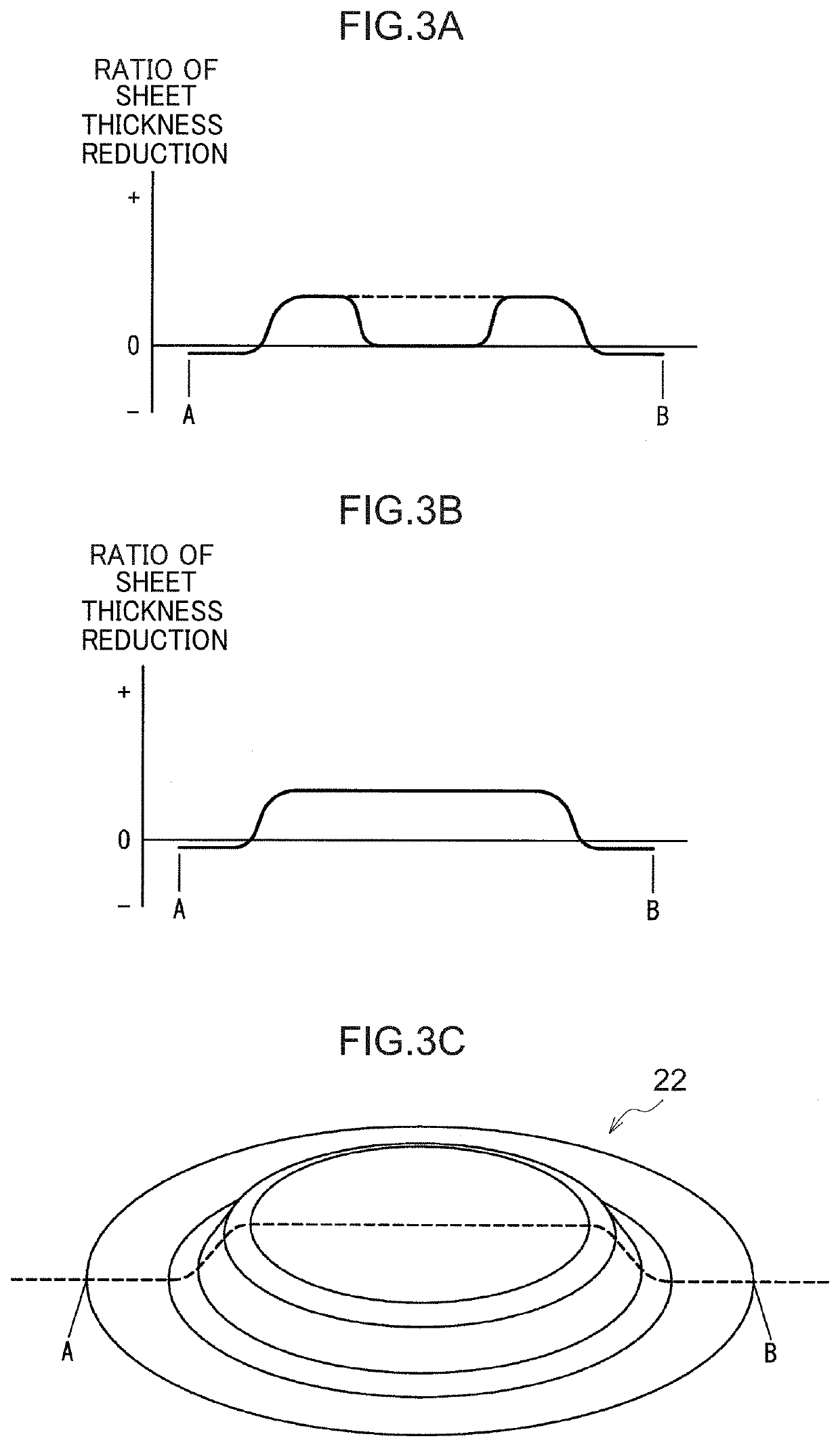
A method of forming a metal sheet into a target shape by press-forming, such that the metal sheet is formed into an intermediate shape that is different from the target shape and then the target shape is formed from the intermediate shape, the method includes: when forming the intermediate shape from the metal sheet, forming the intermediate shape by forming a first region including at least a portion at which a ratio of sheet thickness reduction from the metal sheet is larger when the target shape is formed via the intermediate shape than when the target shape is formed directly from the metal sheet.

Description

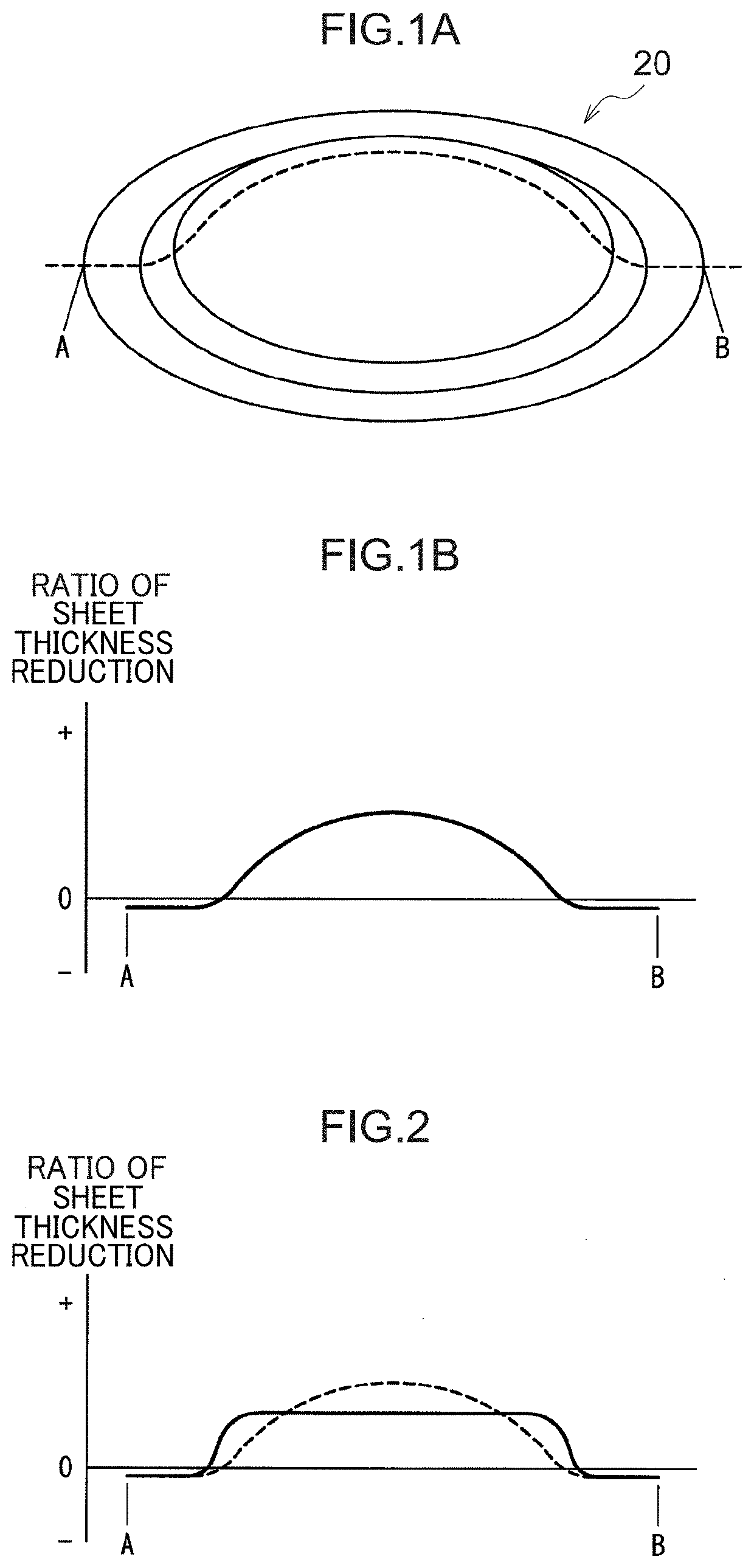
TECHNICAL FIELD[0001]The present invention relates to a metal sheet forming method, an intermediate shape design method, and a metal sheet forming die, computer program, and recording medium.BACKGROUND ART[0002]A reduction in sheet thickness is not necessarily uniform across portions deformed by pressing in press-forming a metal sheet. For example, when a metal sheet is press-formed to form a bulging portion of protrusion shape, the greatest sheet thickness reduction occurs at an apex portion in the bulging portion, and necking (localized narrowing) or cracking sometimes occurs. There is accordingly demand for technology to distribute sheet thickness reduction over the entire component and to utilize material to the maximum (completely use material). In particular with high tensile strength steel, cracking occurs even when there is a slight reduction in sheet thickness. It is therefore necessary to lower the maximum value of the ratio of sheet thickness reduction in the metal sheet....

Claims


Application Information

Patent Timeline
IPC IPC(8): G06F30/23B21D22/24
CPCG06F30/23B21D22/24B21D22/00B21D22/26
Inventor TANAKA, YASUHARUMIYAGI, TAKASHIOGAWA, MISAO
Owner NIPPON STEEL CORP
Why Eureka
Try Eureka