

Oscillating piston-type compressor
- Summary
- Abstract
- Description
- Claims
- Application Information
AI Technical Summary
Benefits of technology
Problems solved by technology
Method used
Image

Examples
embodiment of invention
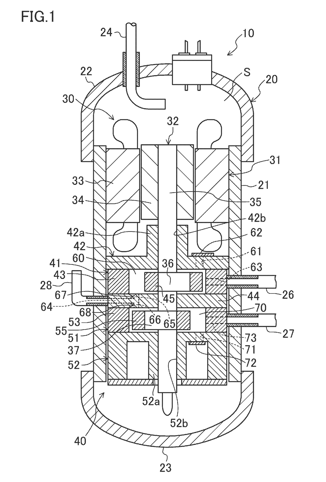
[0051]FIG. 1 is a schematic vertical cross-sectional view of an oscillating piston-type compressor (10) (hereinafter simply referred to as the compressor (10)) according to the embodiment.
[0052]The compressor (10) is connected to, for example, a refrigerant circuit (not shown) of an air conditioner switching between cooling and heating. That is to say, the compressor (10) sucks and compresses the fluid (refrigerant) of the refrigerant circuit, and discharges the compressed refrigerant to the refrigerant circuit. The refrigerant circuit allows a refrigerant to circulate therethrough to perform a refrigeration cycle. Specifically, during a heating operation, the refrigeration cycle is performed in such a manner that a refrigerant compressed by the compressor (10) condenses in an outdoor heat exchanger, and the condensed refrigerant is decompressed at an expansion valve and then evaporates in an indoor heat exchanger. During a heating operation, the refrigeration cycle is performed in ...
embodiment
Other Modifications of Embodiment
Another Modification 1
[0143]Another Modification 1 has the same configuration as the embodiment, except the mechanism for performing an injection operation.
[0144]The compression mechanism (40) includes an injection mechanism (160) configured to perform an injection operation in each compression unit (41, 51). The configuration of the injection mechanism (160) will be described with reference to FIGS. 14 to 16. The injection mechanism (160) includes an introduction passage (161) configured to introduce an intermediate-pressure fluid into each cylinder chamber (60,70) (precisely, into the compression chamber (75)), and an opening / closing mechanism (170) configured to open / close the introduction passage (161). The introduction passage (161) and the opening / closing mechanism (170) in this modification are provided to the middle plate (44).
[0145]The introduction passage (161) includes a main introduction passage (162) extending inward from the outer perip...
modification 1
Advantages of Modification 1
[0167]According to the modification 1, the communication groove (180) constitutes a part of the communication passage (185) for introducing the low pressure refrigerant into the back surface side of the valve body (171). The communication groove (180) can be formed easily by forming a groove in the axial end surface (the upper surface) of the middle plate (44). This can simplify the configuration of the communication passage (185) and reduce the cost for forming the configuration.
[0168]The injection mechanism (160) applies the pressure of the suction chamber (74) of the first cylinder chamber (60) to the back pressure chamber (176). Therefore, according to the difference between the low pressure and the intermediate pressure of the refrigerant, the valve body (171) can reliably be driven between the opened position and the closed position. As a result, switching of the injection operation can be performed, reliably.
[0169]In the injection mechanism (160), ...
PUM
 Abstract
Description
Claims
Application Information