Drill bit for percussive drilling, a drill bit assembly, and a method for manufacturing such a drill bit

a percussive drilling and drill bit technology, applied in drill bits, drilling accessories, earthwork drilling and mining, etc., can solve the problems of weakening the structure of the pile, the fluid may travel long distances along certain ground formations, and the pile is less capable of supporting the structure on top, so as to facilitate the flow of fluid through the lateral flushing channel, enhance the pressure differential, and minimize the deflection

Active Publication Date: 2021-05-18
ROBIT OYJ
View PDF16 Cites 0 Cited by
  • Summary
  • Abstract
  • Description
  • Claims
  • Application Information

AI Technical Summary

Benefits of technology

[0004]An object of the present disclosure is to provide a drill bit and a drill bit assembly with which the problems associated to drilling in sensitive grounds conditions can be overcome or effectively alleviated. A further object of the disclosure to provide a method of manufacturing such drill bit.
[0006]The disclosure is based on the idea of providing a lateral flushing channel extending from a central flushing channel of a drill bit head portion to the circumference thereof in such a way that that the flushing fluid exiting the channel may be directed for enhancing a pressure differential between the surrounding of the circumference of the head portion and the face surface, while enabling the lateral flushing channel to be formed so as to minimize the deflection required for the flushing fluid to flow from the central flushing channel to the lateral flushing channel.
[0007]An advantage of the disclosure is that flushing fluid flow via the lateral flushing channel is facilitated by providing smooth directional transitions, i.e. a smooth general contour resulting in smaller flow resistance, and consequently, pressure loss, thus increasing the capability of the corresponding flushing fluid flow to convey drill cuttings. This advantage is particularly prominent when drilling deep drill holes requiring a relatively high flushing fluid flow and / or velocity to carry drill cuttings to the surface. As an increased flow rate via the lateral flushing fluid channel increases, a pressure differential between the circumference and the face surface of the head portion is also increased, drawing drill cuttings from the periphery of the face surface along with the flushing fluid flow originating from the lateral flushing fluid channel. Such a pressure differential acts much like a vacuum effect, drawings drill cuttings from ahead of the face surface of the head portion. Consequently, as a synergistic effect, the flow of flushing fluid via the drill bit face surface can be decreased, thus reducing the risk associate with drilling in sensitive ground conditions. Moreover, providing a lateral flushing channel according to the disclosure enables flushing fluid flow to be directed towards the shank portion, i.e. the surface, even in connection with drill bits having a relatively large diameter with respect to the height thereof.

Problems solved by technology

It has been recognized that using flushing fluid might cause problems when drilling in sensitive ground conditions.
In soft ground, the flushing fluid may remove an excessive amount ground surrounding the drill bit, which is known as over-drilling.
This is particularly problematic when drilling piles to the ground, as a too big drill hole does not support the pile in a desired manner, making the pile less capable of supporting a structure on top of it.
Another problem associated with using flushing in sensitive ground conditions is that the flushing fluid may travel long distances along certain ground formations, such as clay formations.
Consequently, in densely built areas, flushing fluid may unexpectedly travel up to existing piles or foundations and weaken their structure.

Method used


Image

  • Drill bit for percussive drilling, a drill bit assembly, and a method for manufacturing such a drill bit
  • Drill bit for percussive drilling, a drill bit assembly, and a method for manufacturing such a drill bit
  • Drill bit for percussive drilling, a drill bit assembly, and a method for manufacturing such a drill bit

Examples


Embodiment Construction

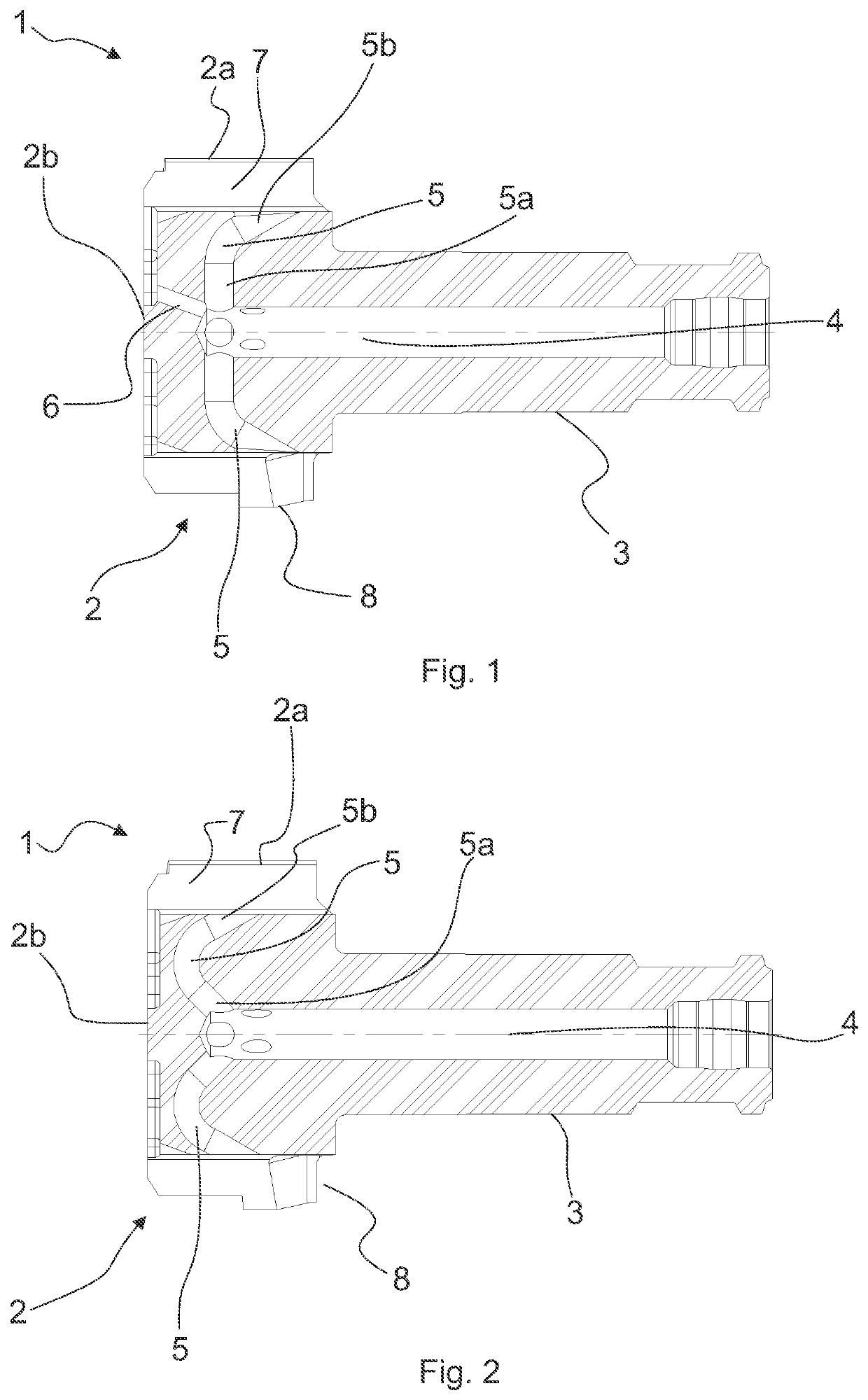
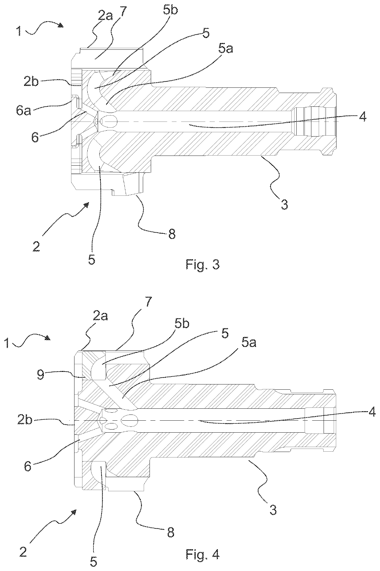
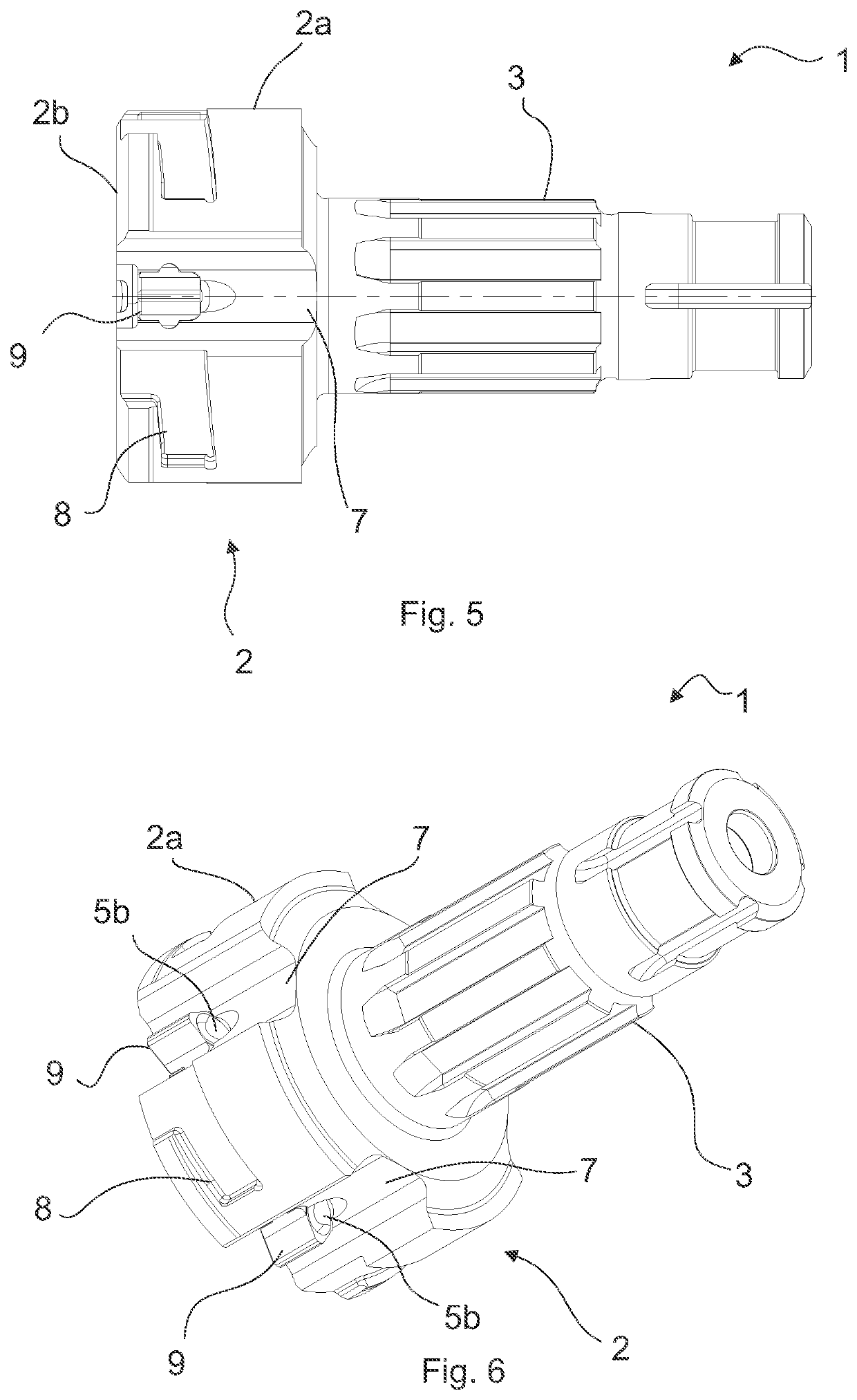
[0013]FIG. 1 illustrates a cut view of drill bit 1 comprising a head portion 2 having a circumference 2a and face surface 2b. Furthermore, a shank portion 3 extends longitudinally from the head portion 2 in a direction opposite to the face surface 2b. A central flushing channel 4 extends longitudinally through the shank portion 3 and a distance within the head portion 2. From the central flushing channel 4, a lateral flushing channel 5 extends up to the circumference 2b of the head portion 2. A first portion of the lateral flushing channel 5a extends in direction transverse to the central flushing channel 4, whereas a second portion 5b of the lateral flushing channel 5 is inclined, in a flowing direction of the flushing fluid, towards the shank portion 3, with respect to the first portion 5a of the lateral flushing channel 5. A smooth transition between the first and second portions 5a, 5b is provided. The drill bit 1 is further equipped with a face surface flushing channel 6, exten...


PUM


Abstract

A drill bit, drill bit assembly and related methods of manufacture as disclosed involve a head portion having a circumference and a face surface, and a shank portion extending longitudinally from a side of the head portion opposite to the face surface. A central flushing channel extends longitudinally through the shank portion and a distance within the head portion, and a lateral flushing channel extends from the central flushing channel to the circumference of the head portion. A first portion of the lateral flushing channel is inclined, in a flushing fluid flowing direction, towards the face surface with respect to said second portion, and correspondingly, a second portion is inclined, in a flushing fluid flowing direction, towards the shank portion.

Description

FIELD OF THE DISCLOSURE[0001]The present disclosure relates to drill bits for percussive drilling, and more particularly to such drill bits where flushing fluid is conducted via a lateral flushing fluid channel. The present disclosure further concerns a drill bit assembly having such a drill bit and a method for manufacturing such a drill bit assembly.BACKGROUND OF THE DISCLOSURE[0002]Flushing fluid is commonly used to flush drill cuttings from the drill hole, ahead of the drill bit. This enables the drill bit to effectively act on the ground to be drilled instead of on excessive drill cuttings residing in the drill hole.[0003]It has been recognized that using flushing fluid might cause problems when drilling in sensitive ground conditions. In soft ground, the flushing fluid may remove an excessive amount ground surrounding the drill bit, which is known as over-drilling. This is particularly problematic when drilling piles to the ground, as a too big drill hole does not support the ...

Claims


Application Information

Patent Timeline
Patent Type & Authority Patents(United States)
IPC IPC(8): E21B10/38E21B10/62E21B10/60
CPCE21B10/38E21B10/60E21B10/62
Inventor KORTE, PASILEINO, ANTTI
Owner ROBIT OYJ
Why Eureka
Try Eureka