Magnetic tape reading apparatus, operation method of magnetic tape reading apparatus, and program

a reading apparatus and magnetic tape technology, applied in the field operation method of magnetic tape reading apparatus, and program, can solve the problems of not being disclosed, reducing the signal-to-noise ratio of reproducing signals, and data reading and tracking control with respect to magnetic tapes may not be synchronously performed, so as to prevent a deterioration in the reliability of data read from tracks

Active Publication Date: 2020-10-01
FUJIFILM CORP
View PDF0 Cites 1 Cited by
  • Summary
  • Abstract
  • Description
  • Claims
  • Application Information

AI Technical Summary

Benefits of technology

[0006]An object of one embodiment of the invention is to provide a magnetic tape reading apparatus capable of preventing a deterioration in reliability of data read from tracks by a linear scan method, compared to a case where data is read by only one time of reading from tracks by a linear scan method, an operation method of a magnetic tape reading apparatus, and a program.
[0026]According to one embodiment of the invention, compared to a case where data is read by reading only one time from the track by a linear scan method, an effect of preventing a deterioration in reliability of data read from tracks by the linear scan method is obtained.

Problems solved by technology

However, JP1991-132901A (JP-H3-132901A) does not disclose a solution in a case where a reproducing signal is omitted.
However, a technology disclosed in JP1997-171605A (JP-H9-171605A) is a technology using a helical scan method, and accordingly, reading of data and tracking control with respect to a magnetic tape may not be synchronously performed.
In addition, the off-track occurring due to deformation and sharp vibration of a magnetic tape, and jitter during running of a magnetic tape also causes a decrease in a signal-to-noise ratio of a reproducing signal.

Method used


Image

  • Magnetic tape reading apparatus, operation method of magnetic tape reading apparatus, and program
  • Magnetic tape reading apparatus, operation method of magnetic tape reading apparatus, and program
  • Magnetic tape reading apparatus, operation method of magnetic tape reading apparatus, and program

Examples


first embodiment

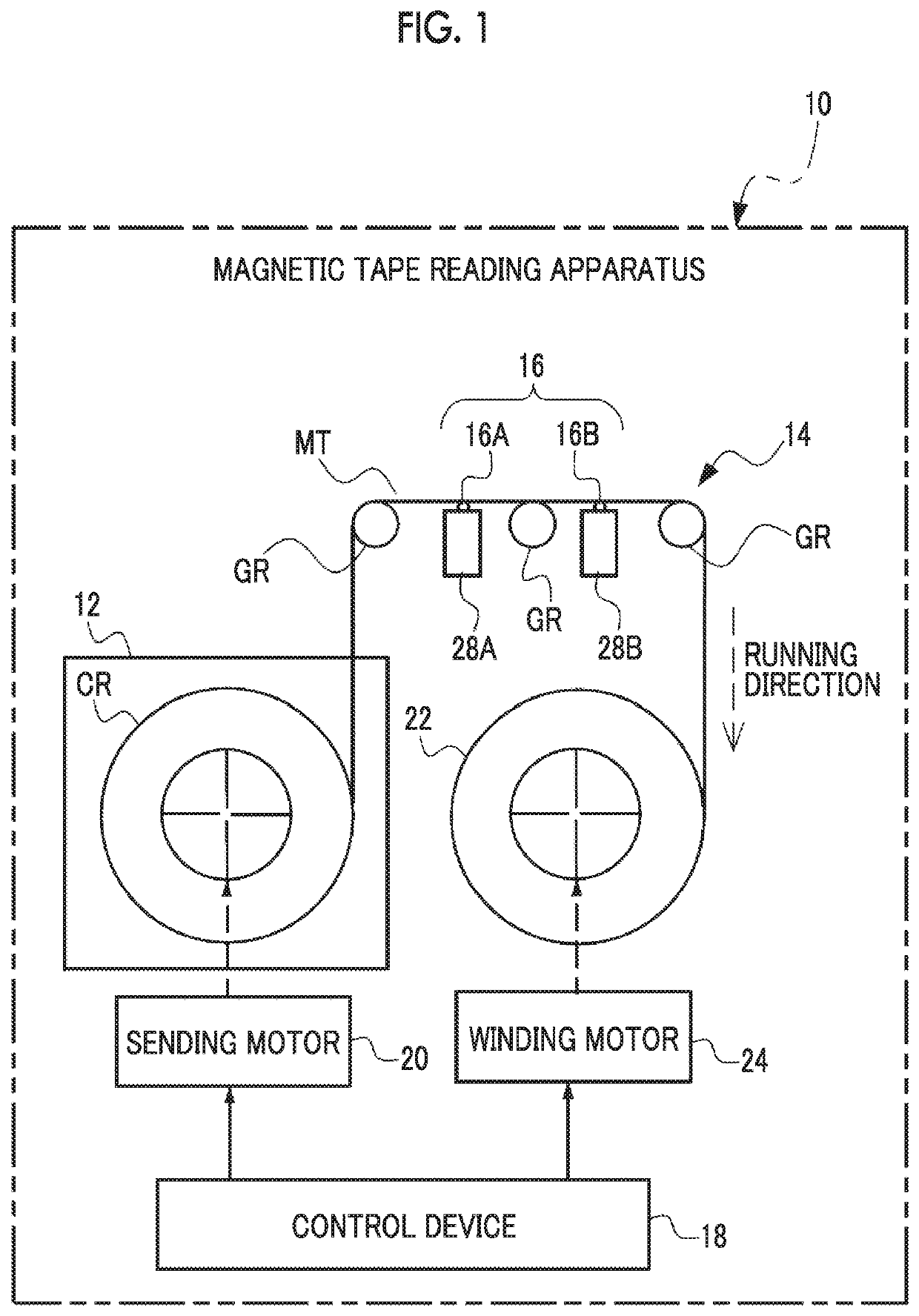
[0051]As an example shown in FIG. 1, a magnetic tape reading apparatus 10 includes a magnetic tape cartridge 12, a transportation device 14, a reading head 16, and a control device 18.

[0052]The magnetic tape reading apparatus 10 is an apparatus which extracts a magnetic tape MT from the magnetic tape cartridge 12 and reads data from the extracted magnetic tape MT by using the reading head 16 by a linear scan method. In the first embodiment according to the technology of the disclosure, the reading of data indicates the reproducing of data. In the following description, data read by the reading head 16 is also referred to as a “reproducing signal”.

[0053]The magnetic tape MT is generally manufactured by forming a magnetic layer including a ferromagnetic powder and any one or more kinds of additives on a non-magnetic support. Non alignment, longitudinal alignment, and vertical alignment can be applied to the magnetic layer. The magnetic layer and the like will be described in detail.

Ma...

second embodiment

[0231]In the first embodiment, a case where the reading target region of data by the reading head 16 is only the track region 30 has been described, but in a second embodiment according to the technology of the disclosure, a case in which the plurality of track regions 30 are reading target regions of data will be described. In the second embodiment according to the technology of the disclosure, the same reference numerals are used for the same constituent elements as those in the first embodiment, and the description thereof is omitted. Hereinafter, the parts different from the first embodiment will be described.

[0232]As shown in FIG. 12 as an example, the magnetic tape MT according to the second embodiment according to the technology of the disclosure is different from the magnetic tape MT according to the first embodiment, in that the plurality of track regions 30 are provided in the tape width direction. In the magnetic tape MT according to the second embodiment according to the...

third embodiment

[0247]In the second embodiment, the embodiment in which the plural times of reading is realized by performing the reading of data by the upstream side reading element 26A and the downstream side reading element 26B has been described, but in a third embodiment according to the technology of the disclosure, a case where the plural times of reading is performed by a single reading element will be described. In the third embodiment according to the technology of the disclosure, the same reference numerals are used for the same constituent elements as those in the second embodiment, and the description thereof is omitted. Hereinafter, the parts different from the second embodiment will be described.

[0248]The magnetic tape reading apparatus 10 according to the third embodiment according to the technology of the disclosure is different from the magnetic tape reading apparatus 10 according to the second embodiment in that a reading head 160 is provided instead of the reading head 16. The r...


PUM

PropertyMeasurementUnit
particle sizeaaaaaaaaaa

Abstract

A magnetic tape reading apparatus including: a reading head which includes a reading unit disposed at a position corresponding to a single track included in a magnetic tape; a controller which controls the reading unit to read data plural times from a specific range of the single track in a running direction of the magnetic tape by a linear scan method; and a synthesis unit which synthesizes a plurality of reproducing signal sequences obtained by reading data plural times from the specific range by the reading unit.

Description

CROSS-REFERENCE TO RELATED APPLICATIONS[0001]This application claims priority under 35 USC 119 from Japanese Patent Application No. 2019-066144 filed Mar. 29, 2019, the disclosure of which is incorporated by reference herein.BACKGROUND1. Technical Field[0002]A technology of the present disclosure relates to a magnetic tape reading apparatus, an operation method of a magnetic tape reading apparatus, and a program.2. Description of the Related Art[0003]JP1991-132901A (JP-H3-132901A) discloses a magnetic recording and reproducing device increasing a signal-to-noise ratio by repeatedly reproducing recorded information and obtaining an arithmetical mean.[0004]However, JP1991-132901A (JP-H3-132901A) does not disclose a solution in a case where a reproducing signal is omitted. The omitted data can be complemented by reproducing plural times. As a technology relating to this, JP1997-171605A (JP-H9-171605A) discloses a digital data reproducing device which reproduces each track plural times ...

Claims


Application Information

Patent Timeline
Patent Type & Authority Applications(United States)
IPC IPC(8): G11B5/49G11B5/55G06F3/06
CPCG06F3/0607G11B2005/0013G06F3/0658G06F3/0682G11B5/5508G11B5/4938
Inventor MUSHA, ATSUSHI
Owner FUJIFILM CORP
Why Eureka
Try Eureka