Insulation injection device

a technology of injection device and insulation material, which is applied in the direction of heat-proofing, other domestic objects, building components, etc., can solve the problems of inaccessibility, poor insulation, high disruptive and expensive approach, and rarely used in practice, and achieve the effect of reducing cost and effor

Inactive Publication Date: 2020-10-15
BUILDING ENVELOPE MATERIALS LLC
View PDF0 Cites 0 Cited by
  • Summary
  • Abstract
  • Description
  • Claims
  • Application Information

AI Technical Summary

Benefits of technology

[0020]The present invention is a building cavity insulation injection device that, in various embodiments, reduces the cost and effort required to create panel holes, avoids blockage of the injection nozzle, ensures that insulation is injected on a desired side of pre-existing insulation, enables injection of a wider variety of types of insulation and / or injection into a wider variety of cavity configurations without exchanging injection guns or nozzles, and avoids dripping of excess insulation on outer surfaces of cavity panels.

Problems solved by technology

These enclosed spaces, referred to herein generically as “building cavities,”“wall cavities,”“ceiling cavities,” or simply as “cavities,” are not accessible, and may be poorly insulated.
Of course, wall and ceiling panels can be removed, and then replaced after new insulation has been installed, but this is a highly disruptive and expensive approach that is rarely used in practice.
However, for large projects such as entire buildings a very large volume of the insulation may be required, which can be problematic and expensive to store and transport.
However, these single component foams have generally yielded inconsistent results, due mainly to an inability to determine and control moisture levels within the cavities.
Nevertheless, it can be time consuming and expensive to drill the large number of panel holes in the wall and ceiling panels that can be required for a large insulation project, such as re-insulating an entire building.
Either of these approaches increases the required time and cost for the project.
Another problem that can arise during the injection of new insulation is that a nozzle can become partially or fully clogged when it is inserted into the cavity and encounters fibers and / or particles of the pre-existing insulation.
Furthermore, in the case of foam-in-place insulation, a blocked flow of precursor material can cause the precursors to react within the nozzle and hoses, so that the gun and hoses are clogged and potentially ruined by the expanded and hardened foam.
Another problem that applies to most insulation injection devices is that they are limited to injecting only a few types of insulation.
For example, an insulation injection gun that is suitable for injecting two-component pour foam insulation may not be suitable for injecting a particulate insulation or a froth foam insulation.
Yet another problem that can be encountered during injection of insulating materials into cavities is that the insulating material can be injected on the wrong side of pre-existing insulation within the cavity, especially in the case of pre-existing unfaced batts of insulation.
Similarly, when the nozzle is inserted into the cavity through the exterior sheathing, it may inadvertently penetrate the existing fibrous insulation, and may deposit the foam either on the interior side of the fibrous insulation or into the center of the fibrous insulation.
Still another problem that can arise when injecting insulating materials into wall and ceiling cavities is that small amounts of insulation material can be inadvertently dripped onto the front of a wall or ceiling panel as the nozzle is withdrawn from a panel hole, or as an excess of expanding foam exudes outward through the panel hole.

Method used


Image

  • Insulation injection device
  • Insulation injection device
  • Insulation injection device

Examples


Embodiment Construction

[0072]The present invention is a building cavity insulation injection device that, in various embodiments, reduces the cost and effort required to create panel holes, avoids blockage of the injection nozzle, ensures that insulation is injected on a desired side of pre-existing insulation, enables injection of a wider variety of types of insulation and / or injection into a wider variety of cavity configurations without exchanging injection guns or nozzles, and avoids dripping of excess insulation on outer surfaces of cavity panels.

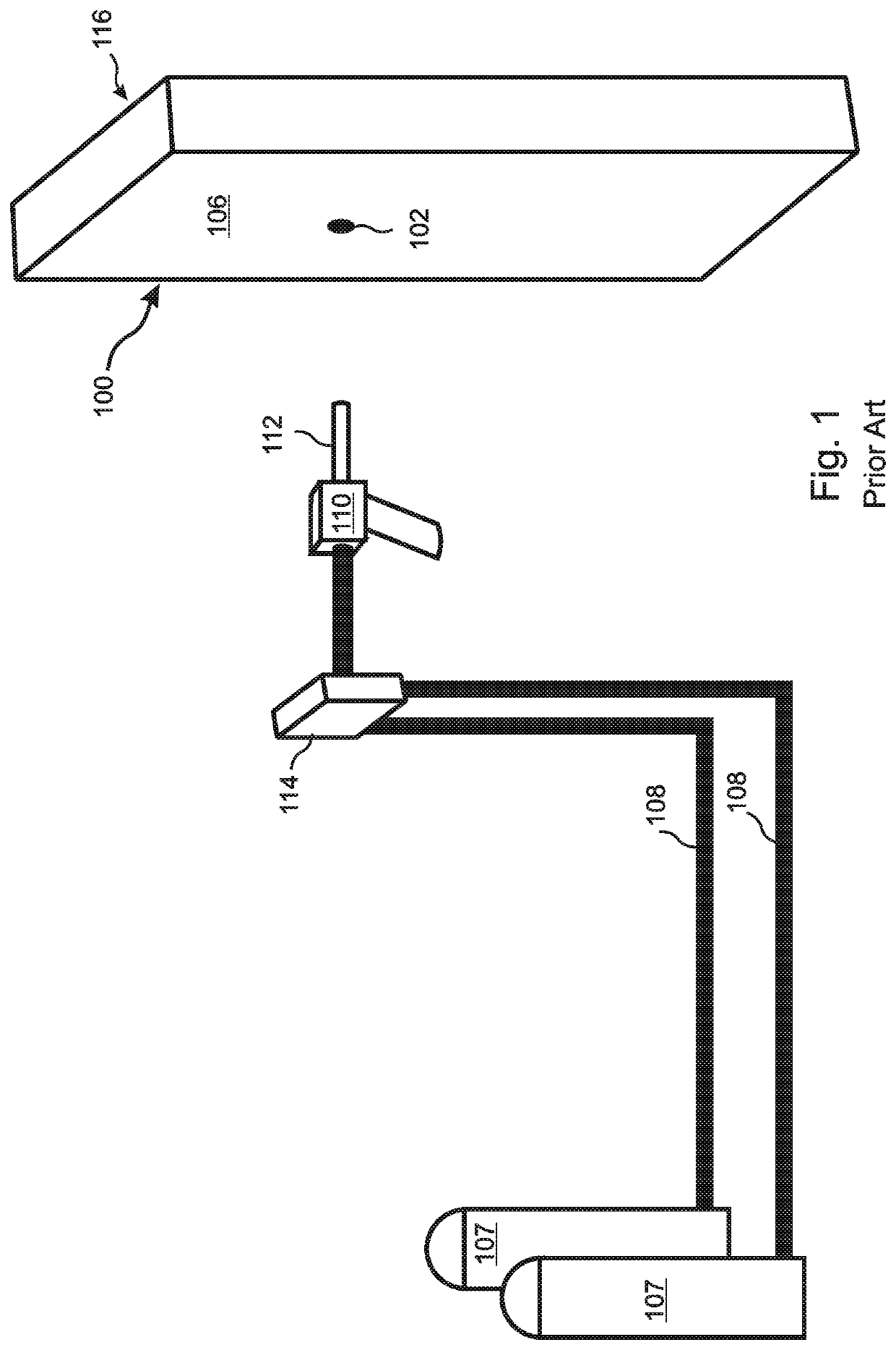
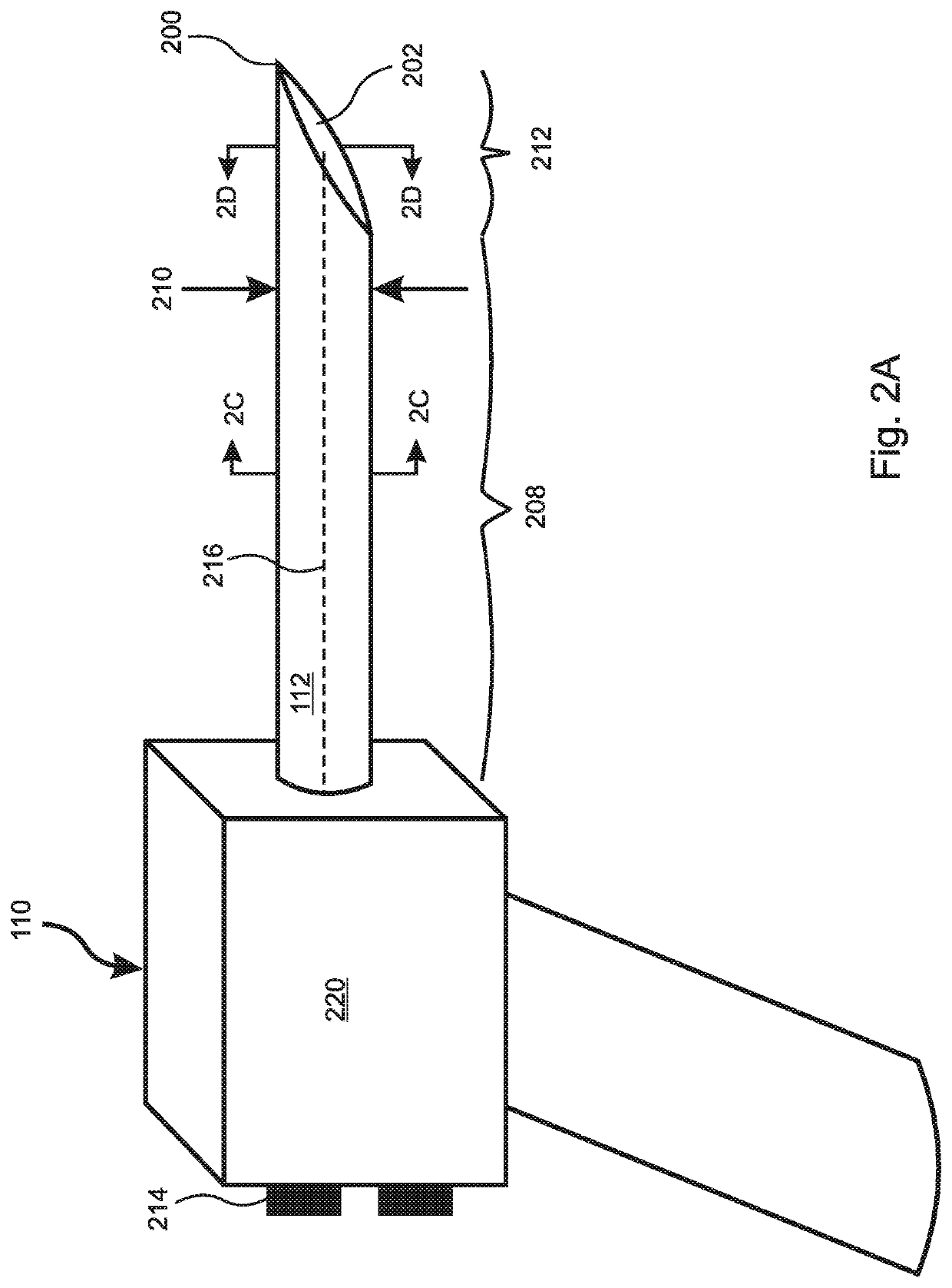
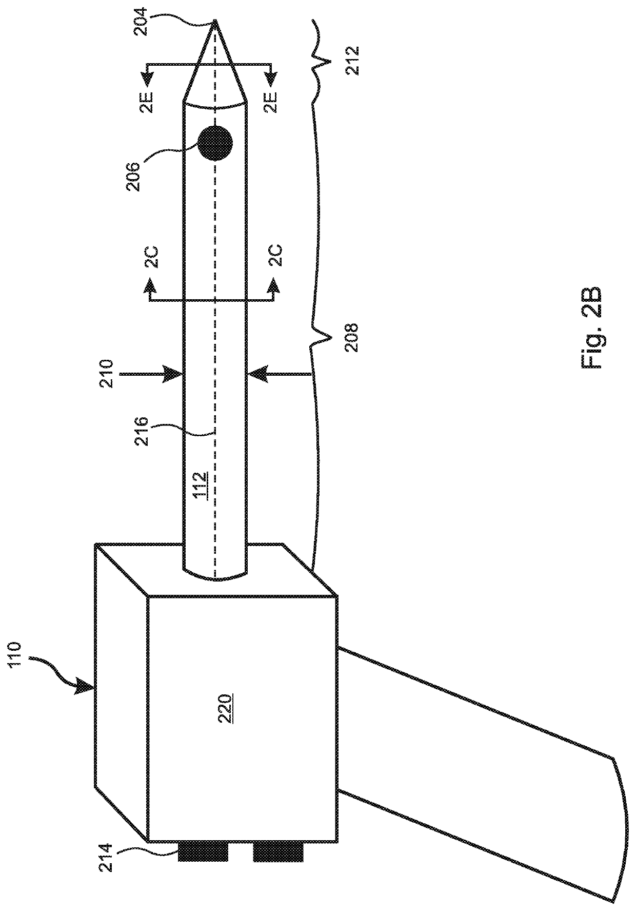
[0073]With reference to FIGS. 2A and 2B, embodiments of the present invention include an insulation dispensing gun 110 having a body 220 and a nozzle 112 that includes input ports 214 configured to receive one or more insulation precursors from precursor vessels (107 in FIG. 1) and to direct the precursors through a central passage of a nozzle 112 and out through a dispensing port provided at the end 202 of the nozzle 112, and / or on a side 206 of the nozzle ...


PUM

PropertyMeasurementUnit
thermal insulationaaaaaaaaaa
areaaaaaaaaaaa
lengthaaaaaaaaaa

Abstract

A thermal insulation injection gun includes a pointed nozzle that prevents blocking of the nozzle by a distal panel of a building cavity and/or by pre-existing insulation within the cavity. In embodiments, the pointed nozzle can be pressed through a panel, thereby forming the injection hole. An enhancement port can be provided through which an enhancing material such as a carrier fluid, particulate or fibrous insulating material, a binder, or a fire retardant can be added and mixed with the insulating material. Embodiments include expanding nozzle wings that can compress pre-existing insulation to create a space on a proximal or distal side thereof for injecting the insulation. A compressible sheath installed over the nozzle can prevent dripping of excess insulation from the panel hole. Exchangeable collars can be used to fix an insertion depth of the nozzle and/or to block selected lateral dispensing ports of the nozzle.

Description

RELATED APPLICATIONS[0001]This application claims the benefit of U.S. Provisional Application No. 62 / 833,721, filed Apr. 14, 2019. This application is also related to U.S. application Ser. No. 15 / 251,783 filed Aug. 30, 2016, which claims the benefit of U.S. provisional application 62 / 222,281 filed Sep. 23, 2015. All of these applications are incorporated herein by reference in their entirety for all purposes.FIELD OF THE INVENTION[0002]The invention relates to apparatus useful for application of insulation materials, and more particularly, to apparatus useful for dispensing insulation through small openings into enclosed cavities.BACKGROUND OF THE INVENTION[0003]Heating and cooling of buildings accounts for approximately 35% of all the energy consumed in the United States of America (USA). Thanks to numerous innovations in construction practices and materials used in new construction, new buildings typically use less than half the energy per square foot of older buildings. However, ...

Claims


Application Information

Patent Timeline
Patent Type & Authority Applications(United States)
IPC IPC(8): E04B1/76B29C44/18B29C44/44B29C44/38
CPCB29L2031/776E04B1/7604B29C44/18B29L2031/10B29C44/386B29C44/44B29K2075/00B29C44/367E04F21/085
Inventor LAMM, DOUGLAS W.BELL, ALEXANDER C.
Owner BUILDING ENVELOPE MATERIALS LLC
Why Eureka
Try Eureka