
Hydraulic fracturing pump system

a pump system and hydraulic technology, applied in the direction of fluid removal, earth-moving drilling, borehole/well accessories, etc., can solve the problems of bulky and heavy pumps and associated engines

Inactive Publication Date: 2020-10-15
THE MODERN GROUP
View PDF0 Cites 137 Cited by
  • Summary
  • Abstract
  • Description
  • Claims
  • Application Information

AI Technical Summary

Benefits of technology

The patent describes a system for fracturing a subsurface formation using a transport unit, an electric motor, a fracking pump, and an oil tank. The oil tank is mounted on the transport unit and is supported by beams that also support the motor and pump. The system also includes a lubricating circuit for the hydraulic fracturing equipment, which uses an oil pump, a variable frequency drive, and a safety valve. The system can be easily moved and can be powered by a battery. The technical effects of the patent include improved efficiency and flexibility in fracturing operations and reduced risk of hydraulic collapse.

Problems solved by technology

Regardless of whether diesel or electric power is used to produce the pressures required for hydraulic fracturing, the pumps and associated engines tend to be bulky and heavy.

Method used


Image

  • Hydraulic fracturing pump system
  • Hydraulic fracturing pump system
  • Hydraulic fracturing pump system

Examples


Embodiment Construction

[0018]It is to be understood that the following disclosure provides many different embodiments, or examples, for implementing different features of various embodiments. Specific examples of components and arrangements are described below to simplify the present disclosure. These are, of course, merely examples and are not intended to be limiting. In addition, the present disclosure may repeat reference numerals and / or letters in the various examples. This repetition is for the purpose of simplicity and clarity and does not in itself dictate a relationship between the various embodiments and / or configurations discussed.

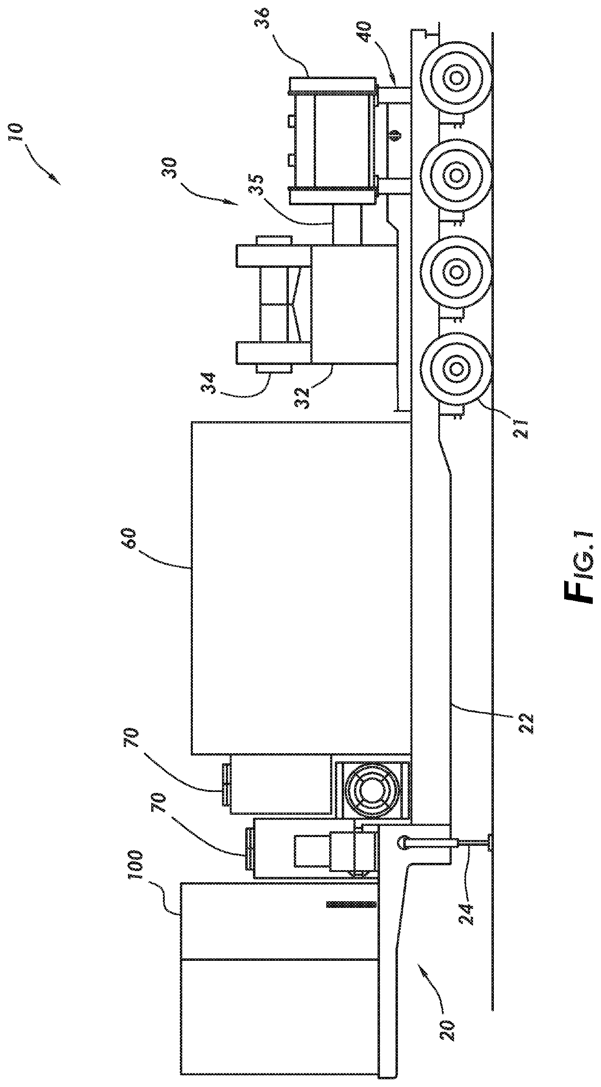
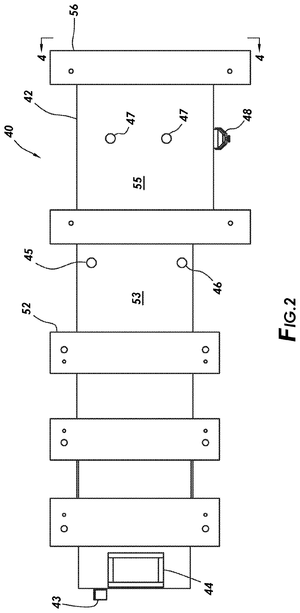
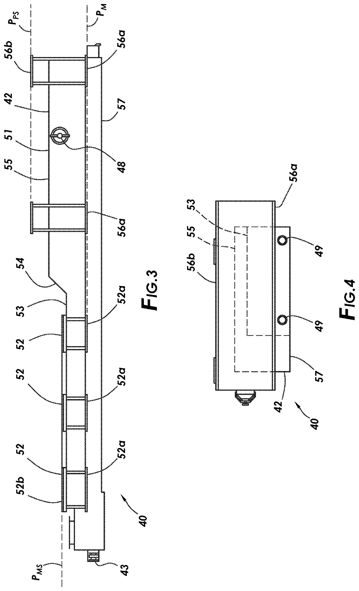
[0019]Referring initially to FIG. 1, transportable hydraulic fracturing system 10 in accordance with some embodiments may comprise several components including but not limited to: transport unit 20, pump unit 30, tank and beam assembly 40, variable frequency drive (VFD) house 60, condensers 70 and control valve system 100. Transport unit 20 may comprise a trailer confi...


PUM


Abstract

A system for fracturing a subsurface formation may comprise a transport unit with hydraulic legs, an electric motor mounted on the transport unit, a fracking pump mounted on the transport unit and configured to be powered by the electric motor, and an oil tank mounted on the transport unit such that the motor and the fracking pump are above the oil tank. The oil tank may have a first tank height under the pump and a second tank height under the motor and the first tank height may be greater than the second tank height. The oil tank, motor support beam, and pump support beam may form a single structural unit. The system may also include an oil pump for pumping lubricating oil through the fracking pump, an electric motor configured to drive the oil pump, a variable frequency drive configured to control the electric motor.

Description

CROSS-REFERENCE TO RELATED APPLICATIONS[0001]This application is a nonprovisional application which claims priority from U.S. provisional application No. 62 / 833,385, filed Apr. 12, 2019, which is incorporated by reference herein in its entirety.[0002]Technical Field / Field of the Disclosure[0003]The present disclosure relates to apparatus and methods for use in hydraulically fracturing subsurface formations.BACKGROUND OF THE DISCLOSURE[0004]Hydraulic fracturing may be used to increase hydrocarbon production from some subsurface formations. Hydraulic fracturing entails injecting fluid into a wellbore at a pressure sufficient to cause fissures in the formation surrounding the wellbore. The injected fluid may be a slurry or mixture containing any of a variety of water-, oil-, or gas-based fluids and a proppant and / or other desired additives.[0005]In some instances, the fracturing fluid is pressurized at the surface by high-pressure pumps powered by diesel engines. In other instances, el...

Claims


Application Information

Patent Timeline
IPC IPC(8): E21B43/26
CPCE21B43/26
Inventor MARKHAM, GARY
Owner THE MODERN GROUP
Learn More