

Drive-torque amplifier for a moving shaft
a technology of torque amplifier and moving shaft, which is applied in the direction of fluid gearing, shaft, belt/chain/gearing, etc., can solve the problems of inability to use when attached to a machine, many of its parts are subject to continuous wear, and are difficult to maintain
- Summary
- Abstract
- Description
- Claims
- Application Information
AI Technical Summary
Benefits of technology
Problems solved by technology
Method used
Image

Examples
Embodiment Construction
[0006]As a solution to the disadvantages and problems mentioned above, this invention was developed, the inventive step of which is the use of the mechanical advantage which involves the application of Pascal's Law, in this case, for rotary movement.
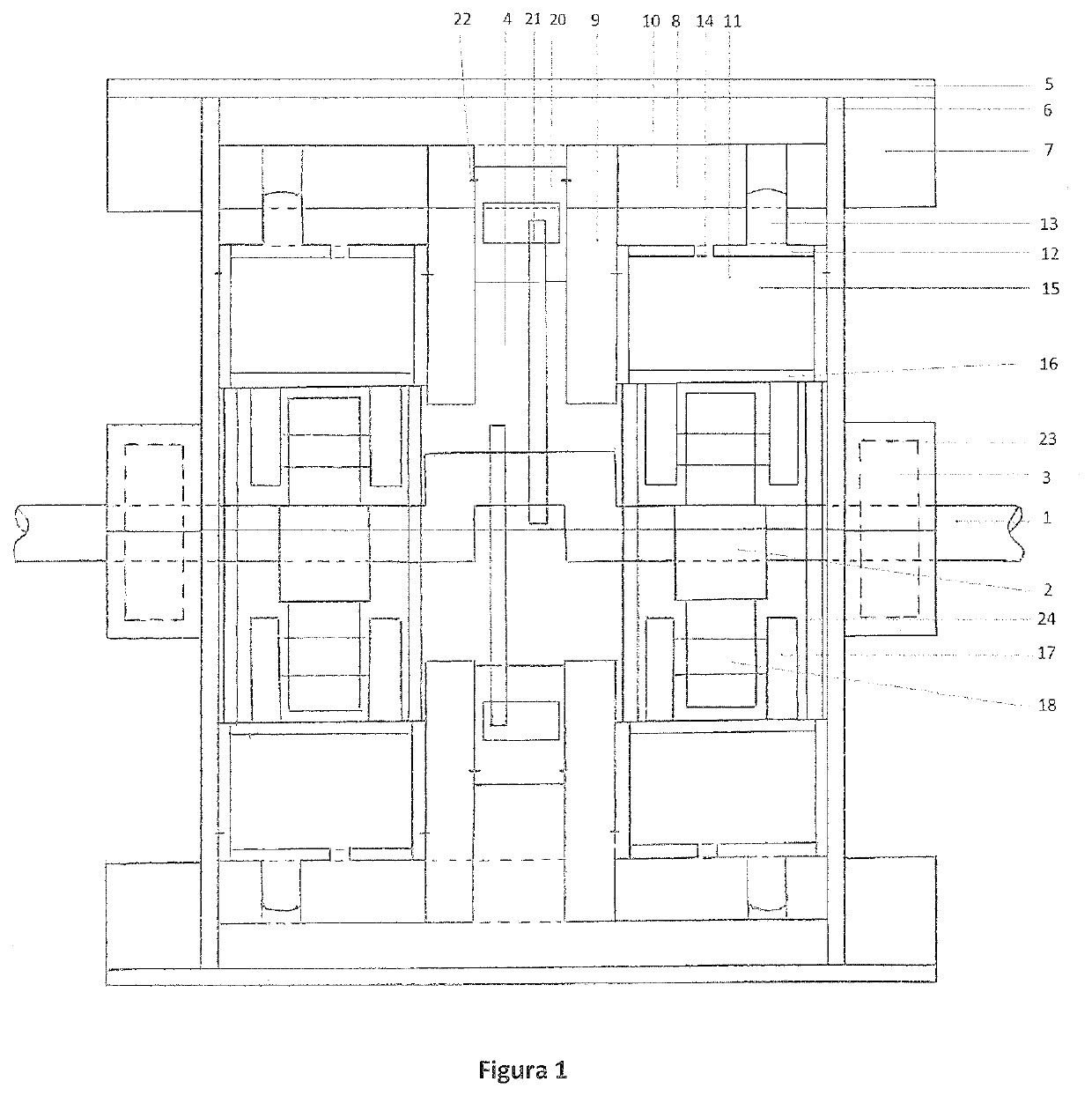
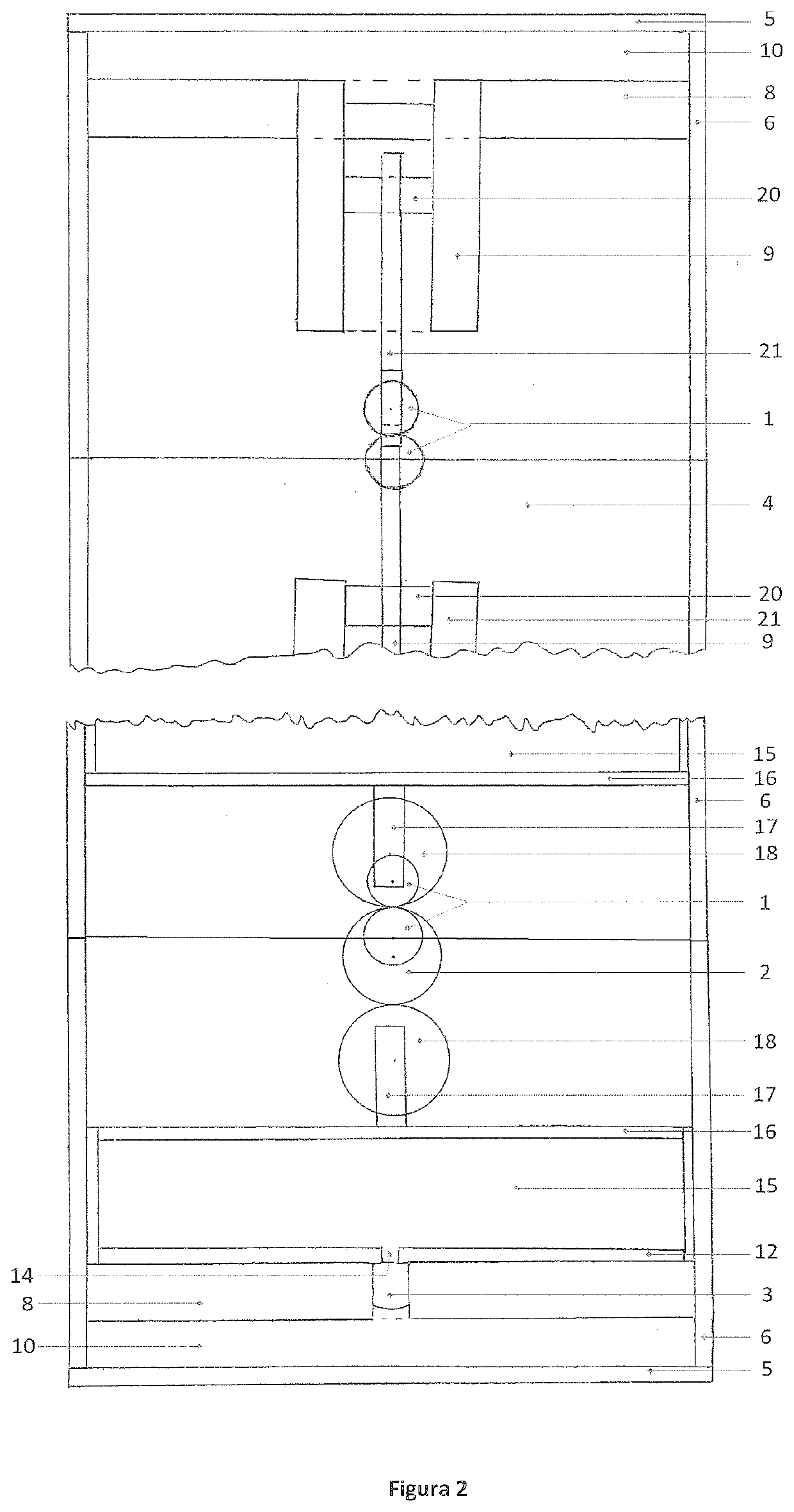
[0007]The device is a machine that amplifies the torque of a rotating shaft due to the effect of energy in the form of rotary movement that it receives from the outside, through the joint work of at least one mechanical actuator (cam), one hydraulic actuator (amplified linear force that provides the application of Pascal's Law) and one piston-connecting rod-crankshaft mechanism); it is by mechanical considerations, a two-stroke motor (compression and recharge), of at least one pair of horizontally opposed pistons, that is, an 180-degree V-motor, which is composed of at least one pair of identical units on either side of a crankshaft with at least one central elbow for connecting rods, with at least one eccentric circular cam fixed to the...
PUM
 Abstract
Description
Claims
Application Information