
Method and system for high resolution digitized display

a digitized display and high resolution technology, applied in the field of high resolution digitized display, can solve problems such as poor image quality, achieve the effects of increasing dynamic digitized wavefront resolution, enhancing focal/accommodation cues of eyepieces, and increasing beamlet density

Active Publication Date: 2020-10-15
MAGIC LEAP INC
View PDF1 Cites 1 Cited by
  • Summary
  • Abstract
  • Description
  • Claims
  • Application Information

AI Technical Summary

Benefits of technology

This approach significantly improves image resolution, reducing the 'screen door' artifact and enhancing depth cues, allowing for higher density of output beamlets without the limitations of thinner substrates, resulting in clearer and more immersive virtual or augmented reality experiences.

Problems solved by technology

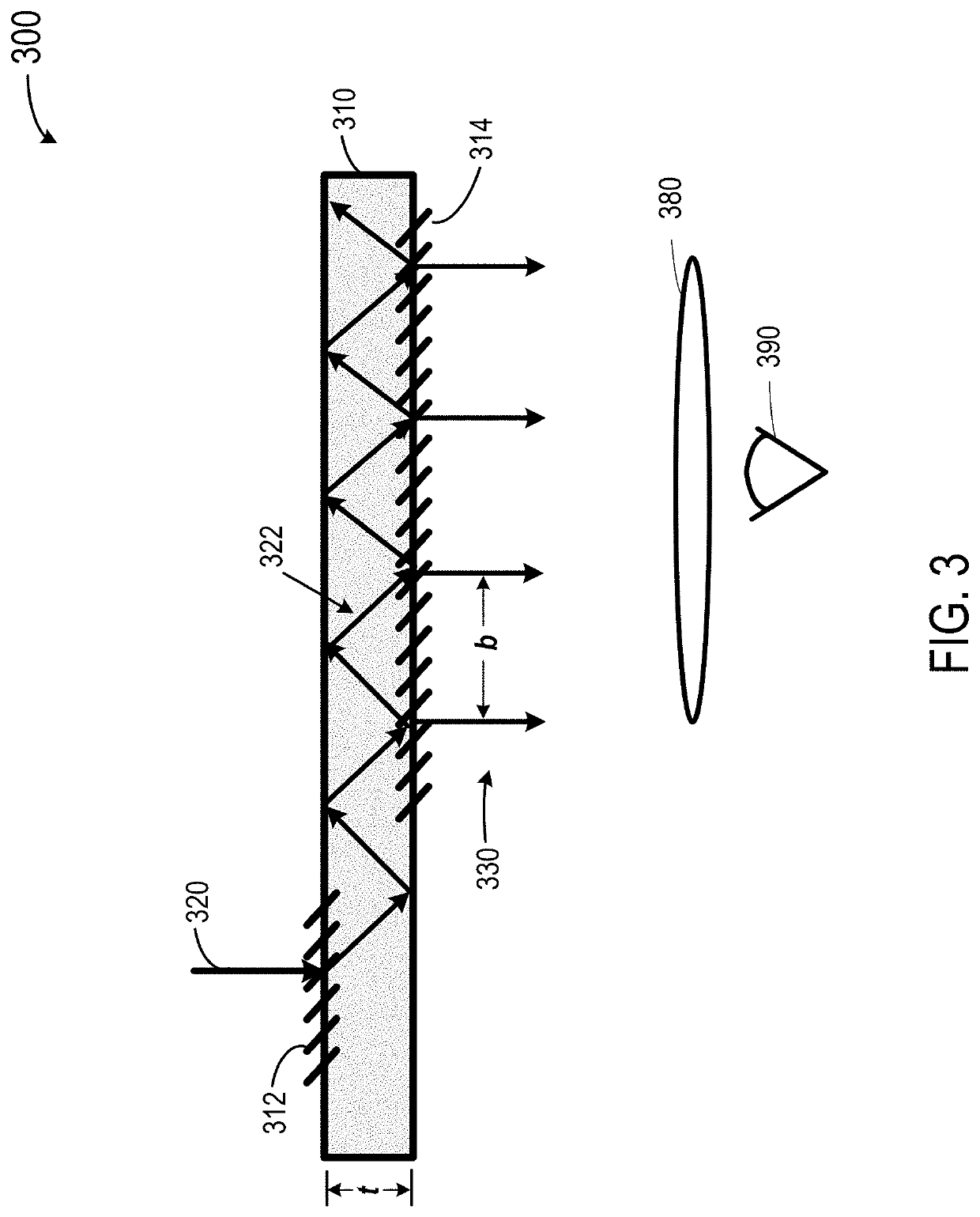
If the density of these output light beamlets is low, i.e., the resolution of the output wavefront is low, then the image quality is poor.

Method used


Image

  • Method and system for high resolution digitized display
  • Method and system for high resolution digitized display
  • Method and system for high resolution digitized display

Examples


Embodiment Construction

[0029]Representative applications of methods and apparatus according to the present application are described in this section. These examples are being provided solely to add context and aid in the understanding of the described embodiments. It will thus be apparent to one skilled in the art that the described embodiments may be practiced without some or all of these specific details. In other instances, well known process steps have not been described in detail in order to avoid unnecessarily obscuring the described embodiments. Other applications are possible, such that the following examples should not be taken as limiting.

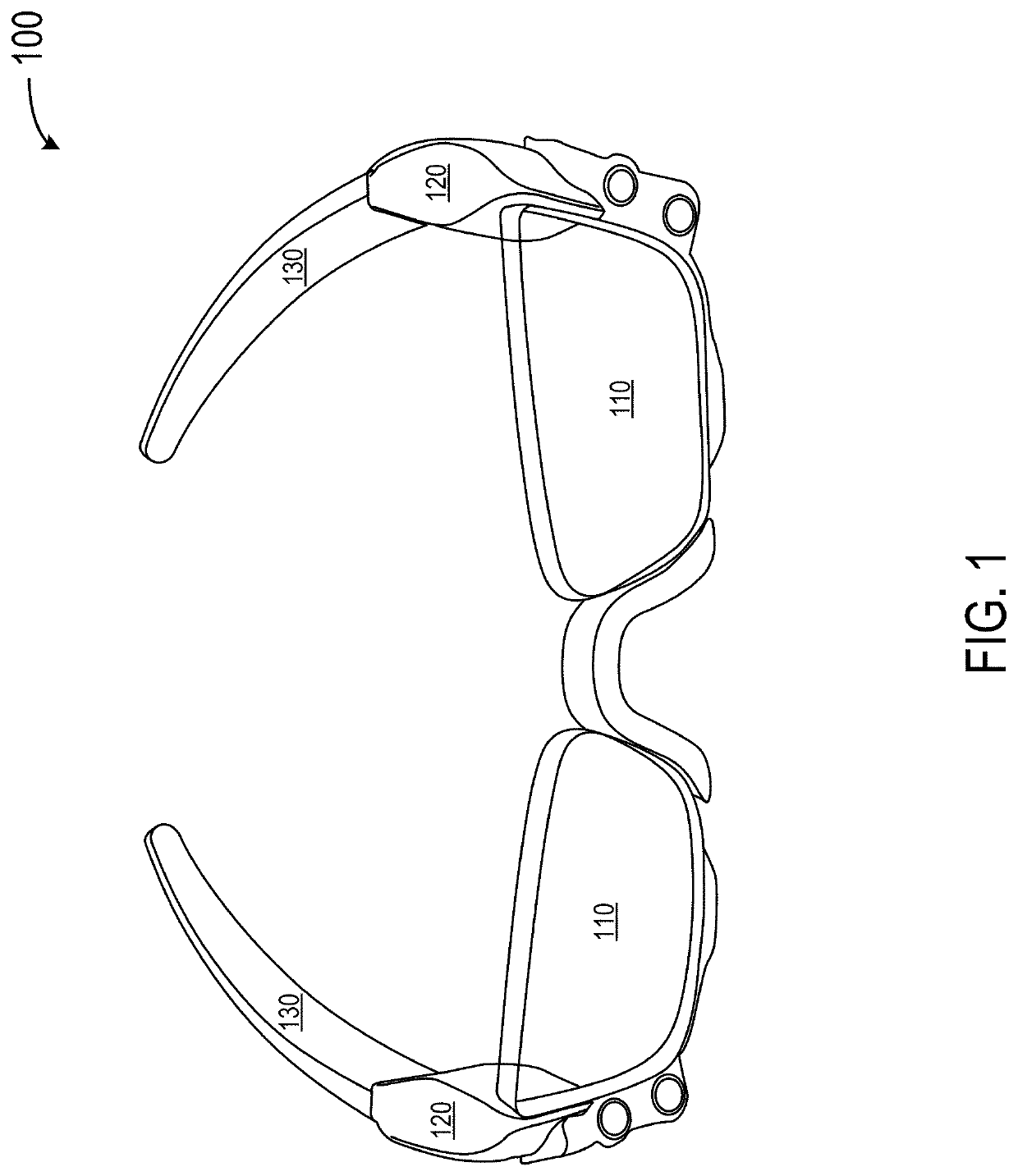
[0030]FIG. 1 is a simplified schematic diagram illustrating a perspective view of an exemplary wearable display device 100 according to some embodiments of the present invention. Wearable display device 100 includes main displays 110. In some embodiments, wearable display device 100 also includes projector assemblies 120, which are integrated into temple arms 1...


PUM


Abstract

A method and system for increasing dynamic digitized wavefront resolution, i.e., the density of output beamlets, can include receiving a single collimated source light beam and producing multiple output beamlets spatially offset when out-coupled from a waveguide. The multiple output beamlets can be obtained by offsetting and replicating a collimated source light beam. Alternatively, the multiple output beamlets can be obtained by using a collimated incoming source light beam having multiple input beams with different wavelengths in the vicinity of the nominal wavelength of a particular color. The collimated incoming source light beam can be in-coupled into the eyepiece designed for the nominal wavelength. The input beams with multiple wavelengths take different paths when they undergo total internal reflection in the waveguide, which produces multiple output beamlets.

Description

CROSS-REFERENCES TO RELATED APPLICATIONS[0001]This application is a divisional of U.S. patent application Ser. No. 15 / 826,315, filed on Nov. 29, 2017, entitled “ METHOD AND SYSTEM FOR HIGH RESOLUTION DIGITIZED DISPLAY,” which is a non-provisional of and claims the benefit of and priority to U.S. Provisional Patent Application No. 62 / 428,510, filed on Nov. 30, 2016, entitled “METHOD AND SYSTEM FOR HIGH RESOLUTION DIGITIZED DISPLAY,” which are hereby incorporated by reference in their entirety for all purposes.BACKGROUND OF THE INVENTION[0002]Modern computing and display technologies have facilitated the development of systems for so-called “virtual reality” or “augmented reality” experiences, wherein digitally produced images or portions thereof are presented in a wearable device to a user in a manner wherein they seem to be, or may be perceived as, real. A virtual reality, or “VR,” scenario typically involves presentation of digital or virtual image information without transparency ...

Claims


Application Information

Patent Timeline
Patent Type & Authority Applications(United States)
IPC IPC(8): G02B27/01F21V8/00G02B30/25
CPCG02B6/0023G02B27/0172G02B2027/0178G02B2027/011G02B2027/0138G02B2027/0147G02B6/0016G02B6/0038G02B6/34G02B6/29329G02B27/106G02B6/0026
Inventor EDWIN, LIONEL ERNESTYEOH, IVAN LI CHUENSCHOWENGERDT, BRIAN T.CURTIS, KEVIN RICHARDWELCH, WILLIAM HUDSONST. HILAIRE, PIERRECHENG, HUI-CHUAN
Owner MAGIC LEAP INC
Learn More