Clipping Machine with Secured Access to the Clipping Region

a clipping machine and secured technology, applied in the field of clipping machines, can solve the problems of restricted space for carrying out cleaning and/or maintenance operations, residue material or scrap of tubular packaging casing might migrate into said gaps, etc., and achieve the effects of low bending stiffness, increased efficiency of clipping machines, and low bending stiffness

Active Publication Date: 2020-10-22
POLY CLIP SYST
View PDF0 Cites 1 Cited by
  • Summary
  • Abstract
  • Description
  • Claims
  • Application Information

AI Technical Summary

Benefits of technology

[0022]The rotational joint of a further preferred embodiment of the inventive clipping machine may be arranged at a position towards a bottom of the portion of the first side wall which is adjacent to the movable housing element. Thus, the center of mass of the movable housing element is located above the axis of rotation in such a way that the torque which the mass of the movable housing element exerts upon its axis of rotation is always directed such that the current position, open or closed, of the movable housing element is stable and maintained without further measures. In other words, when the movable housing element is rotated in the open position, it tends to remain in the open position, and poses no risk of moving into the closed position without external forces applied. Thereby, an unintended closing of the movable housing element and subsequent potential injury of an operator working in the range of movement of the movable housing element can be prevented.
[0023]In a further preferred embodiment of the inventive clipping machine, the movable housing element can further comprise a locking mechanism for releasably locking the movable housing element in the closed position. Such a locking mechanism may act as an additional safety measure to prevent the movable housing element from being opened unintentionally.
[0024]In a further preferred embodiment of the inventive clipping machine, the movable housing element can comprise at least one guide element that prevents the movable housing element from deflecting into the closing region. Such a guide element may be particularly advantageous, when the movable housing element is of relatively low bending stiffness, such as, for example, when the movable housing element is made from the same material having the same thickness as the adjacent portion of the first side wall. The guide element can guide the movable housing element along the adjacent first side wall, so that during movement from the open to the closed position, and vice versa, the movable housing element does not deflect into the closing region of the clipping machine. The guide element can further prevent the movable housing element from deflecting into the closing region of the clipping machine during operation of the machine, when the movable housing element is in the closed position.
[0025]The at least one guide element of a further preferred embodiment of the inventive clipping machine can further be disposed on a side of the movable housing element that faces the filling means, and further extends beyond the outer rim of the movable housing element. The guide element thereby provides form closure against the adjacent side wall, which prevents the movable housing element from deflecting into the closing region of the clipping machine.
[0026]In a further preferred embodiment of the inventive clipping machine, the first side wall can further comprise at least one stopper element which is disposed on a side of the first side wall which faces the filling means. The stopper element can extend beyond the rim or edge of the first side wall toward the movable housing element, and the stopper element prevents the movable housing element from deflecting in a direction opposite the closing region. The stopper element can therefore engage the movable housing element and provide form closure, so that the movable housing element may not deflect in a direction opposite the closing region. Such a stopper element may be particularly advantageous, when the movable housing element is of relatively low bending stiffness, such as, for example, when the movable housing element is made from the same material having the same thickness as the adjacent portion of the first side wall.
[0027]The movable housing element of the inventive clipping machine may in a further preferred embodiment further comprise a centering mandrel which is configured for centering an assembly of multiple filling means on the clipping machine. Such an assembly may increase the efficiency of the clipping machine, as production may speedily be switched between different packaging casings and filling materials.

Problems solved by technology

However, due to the small clearances between the side wall and the first displacer unit as well as between the side wall and the casing brake assembly arranged at the downstream end of the filling tube, the space for carrying out, for example, cleaning and / or maintenance operations is restricted.
Furthermore, residue material or scrap of the tubular packaging casing might migrate into said gaps.

Method used


Image

  • Clipping Machine with Secured Access to the Clipping Region
  • Clipping Machine with Secured Access to the Clipping Region
  • Clipping Machine with Secured Access to the Clipping Region

Examples


Embodiment Construction

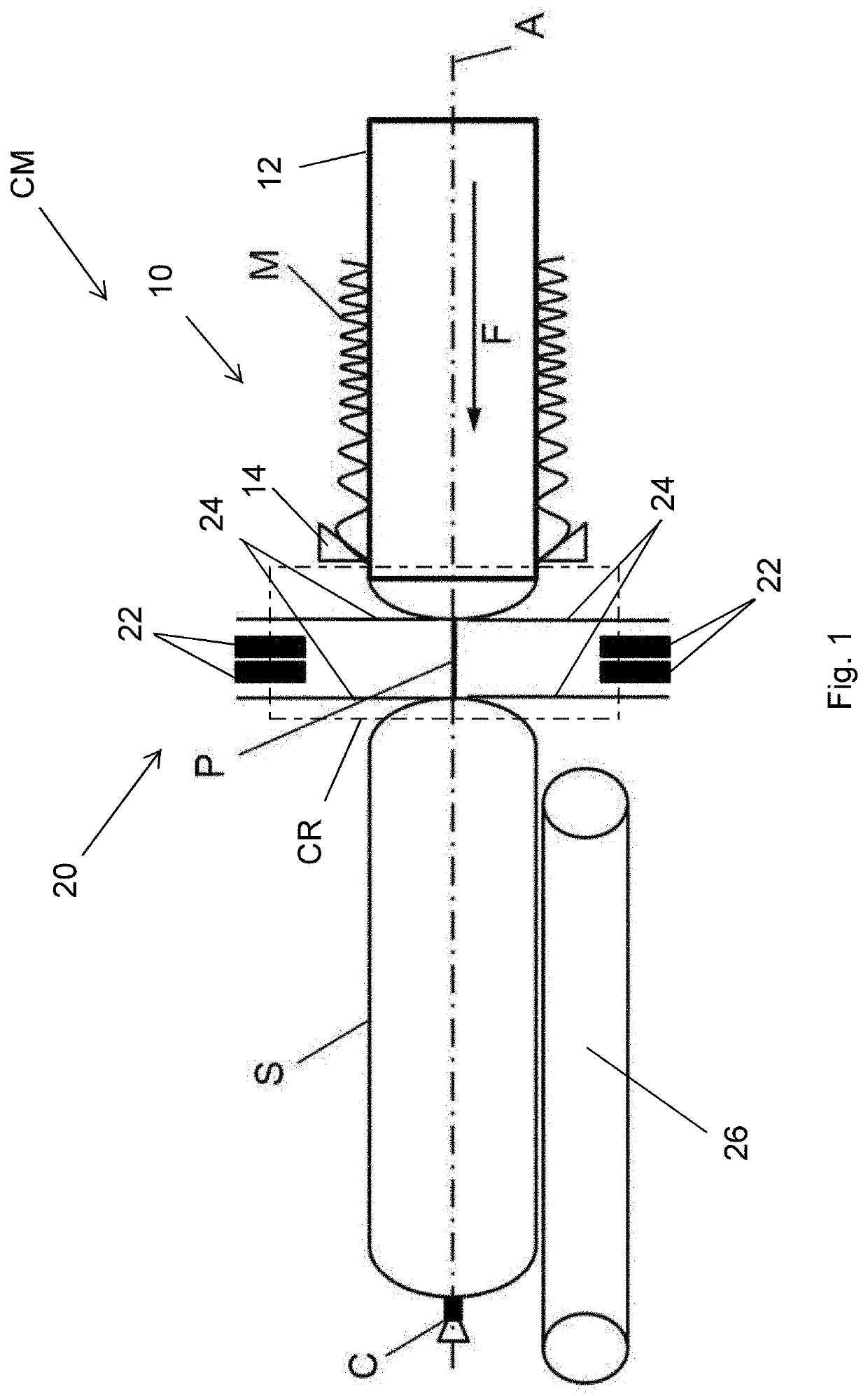
[0043]A clipping machine CM for producing sausage-shaped products S shown in FIG. 1 comprises, as main components, filling means or filling device 10 which comprise a cylindrical filling tube 12 having a longitudinally extending central axis A and being made of a suitable material, like stainless steel. A tubular packaging casing M made of a thin sheet material is stored on the filling tube 12. Clipping machine CM further includes closing means or closing device 20. Closing means 20 comprise two pairs of clipping tools 22 and gathering means 24 for gathering the filled tubular packaging casing M and for forming a plait-like portion P thereto which are arranged downstream filling tube 12. Plait-like portion P is at least approximately free of filling material. Clipping tools 22 comprising at least one punch and one die for closing one closure means, like a closure clip C, are provided for closing the filled tubular packaging casing M by applying said at least one closure means to sai...


PUM

PropertyMeasurementUnit
thicknessaaaaaaaaaa
axis of rotationaaaaaaaaaa
pressureaaaaaaaaaa

Abstract

The present invention relates to a clipping machine for producing sausage-shaped products, like sausages, containing a flowable filling material in a tubular or bag-shaped packaging casing, the machine comprising filling means configured to feed filling material into the casing, and further comprises closing means arranged downstream the filling means, for closing the casing in a closing region. A housing is provided, enclosing at least the closing region, comprising at least a front wall and a first side wall, wherein the front wall is arranged at least substantially parallel to a longitudinally extending axis of the filling means, and further comprises an opening which can be closed by a movable door element, movable between an open position, allowing access to the closing region and a closed position, covering and blocking access to the closing region. The side wall faces the filling means and further comprises a movable housing element, movable between at least an open position and a closed position, wherein the movable housing element comprises an opening for passing through the sausage-shaped products, and wherein the movable housing element enables access from a side of the first side wall to the closing region when in the open position; and wherein the movable housing element covers and blocks access to the closing region when in the closed position.

Description

CROSS-REFERENCE TO RELATED APPLICATION[0001]The present application claims the benefit of priority of European Patent Application No. 19170092.1 filed on Apr. 18, 2020, the contents of which are incorporated herein by reference in their entirety.FIELD OF THE INVENTION[0002]The present invention relates to a clipping machine for producing sausage-shaped products as defined in the preamble of claim 1. In particular, the present invention concerns a clipping machine for producing sausage-shaped products, like sausages, which contain a flowable filling material in a tubular or bag-shaped packaging casing, wherein the clipping machine comprises filling means having a longitudinally extending axis, the filling means configured to feed filling material into the tubular or bag-shaped packaging casing, closing means arranged downstream the filling means, for closing the tubular or bag-shaped packaging casing in a closing region, and a housing enclosing at least the closing region and compris...

Claims


Application Information

Patent Timeline
Patent Type & Authority Applications(United States)
IPC IPC(8): A22C11/12A22C11/00A22C11/02A22C11/10
CPCA22C11/0263A22C11/008A22C11/10A22C11/125A22C11/02B65B9/15B65B51/04B65B59/00
Inventor WEIDENHAUS, BJÖRN
Owner POLY CLIP SYST
Why Eureka
Try Eureka