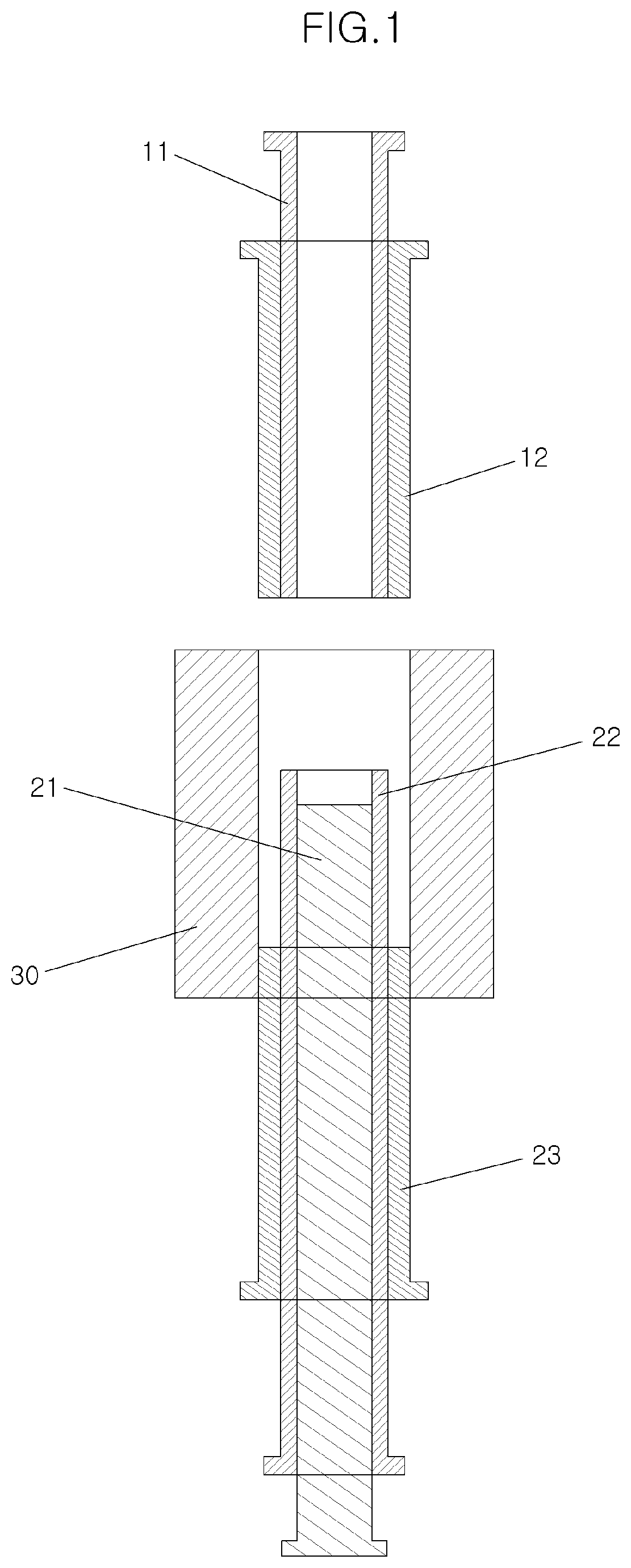
End piece for camshaft

a technology of camshaft and end piece, which is applied in the direction of manufacturing tools, machines/engines, forging/pressing/hammering apparatus, etc., can solve the problems of difficult to form the end piece, and achieve the effect of avoiding problems and achieving cost advantages

Pending Publication Date: 2020-10-22
HYUNDAI MOTOR CO LTD +1
View PDF2 Cites 0 Cited by
  • Summary
  • Abstract
  • Description
  • Claims
  • Application Information

AI Technical Summary

Benefits of technology

[0012]Various aspects of the present invention are directed to providing an end piece for a camshaft, configured for having an advantage in terms of cost and no issues in a joint portion with a camshaft since the end piece is not made entirely of steel, and a method of manufacturing the same, configured for more effectively performing a forming process.

Problems solved by technology

However, it is difficult to form the end piece by powder metallurgy due to the long length of the end piece, and the joint portions between the end piece and the camshaft need to use the same material to bond the end piece to the camshaft by brazing or friction welding.

Method used


Image

  • End piece for camshaft
  • End piece for camshaft
  • End piece for camshaft

Examples


Embodiment Construction

[0036]Reference will now be made in detail to various embodiments of the present invention(s), examples of which are illustrated in the accompanying drawings and described below. While the invention(s) will be described in conjunction with exemplary embodiments, it will be understood that the present description is not intended to limit the invention(s) to those exemplary embodiments. On the contrary, the invention(s) is / are intended to cover not only the exemplary embodiments, but also various alternatives, modifications, equivalents and other embodiments, which may be included within the spirt and scope of the invention as defined by the appended claims.

[0037]The accompanying drawings for illustrating exemplary embodiments of the present invention are referred to gain a sufficient understanding of the present invention, the merits thereof, and the objectives accomplished by the implementation of the present invention.

[0038]In certain embodiments, detailed descriptions of device co...


PUM

PropertyMeasurementUnit
densityaaaaaaaaaa
lengthaaaaaaaaaa
temperatureaaaaaaaaaa

Abstract

A method of manufacturing an end piece for a camshaft may include forming a shape of an end piece to be coupled to a camshaft by compacting steel and powder in a net-shape manner and by sintering steel and a powder compact that are preassembled to each other.

Description

CROSS-REFERENCE(S) TO RELATED APPLICATIONS[0001]The present application claims priority to Korean Patent Application No. 10-2016-0170746, filed on Dec. 14, 2016, the entire contents of which is incorporated herein for all purposes by this reference.BACKGROUND OF THE INVENTIONField of the Invention[0002]The present invention relates to an end piece for a camshaft, and more particularly, to an end piece for a camshaft which is provided at a longitudinal end portion of a camshaft, and a method of manufacturing the same.Description of Related Art[0003]In general, a vehicle engine includes a plurality of pistons disposed between a cylinder block and a cylinder head, and the vehicle engine generates power by a reciprocating motion of the pistons.[0004]The pistons reciprocate by combustion of fuel injected into a combustion chamber. The combustion chamber is opened or closed to be suitable for intake, compression, explosion, and exhaust strokes therein during the combustion of fuel.[0005]T...

Claims


Application Information

Patent Timeline
Patent Type & Authority Applications(United States)
IPC IPC(8): B21D53/84B21C23/08F16H53/02B22F7/08B22F3/03F01L1/047B21K25/00B21K1/06B22F5/00C22C1/05B22F1/10
CPCB22F7/08B21K25/00F01L2810/02B21D53/84B21K1/06F01L1/047F01L2301/00B22F2003/033B22F3/03B22F5/008B21C23/08F01L2303/01F16H53/025C22C1/05C22C33/0214B22F2998/10B21D53/845B22F7/04F01L1/46B22F1/10B22F3/004B22F3/02B22F3/10B22F3/12F01L2303/00B23P2700/02
Inventor KWAK, HYUNG-SEOKLEE, JIN-HYEONKIM, GI-BUMJO, YEONG-CHEOL
Owner HYUNDAI MOTOR CO LTD
Why Eureka
Try Eureka