Thresholds for change identification when comparing imagery

a technology of change identification and imagery, applied in image enhancement, instruments, data processing applications, etc., can solve the problems of limited texture resolution and geometry quality, difficult to update, and provide no robust real-time image data analytics for various consumer and commercial use cases

Pending Publication Date: 2020-10-22
HOVER
View PDF1 Cites 7 Cited by
  • Summary
  • Abstract
  • Description
  • Claims
  • Application Information

AI Technical Summary

Problems solved by technology

However, these 3D models have limited texture resolution and geometry quality, scale, are difficult to up

Method used


Image

  • Thresholds for change identification when comparing imagery
  • Thresholds for change identification when comparing imagery
  • Thresholds for change identification when comparing imagery

Examples


Embodiment Construction

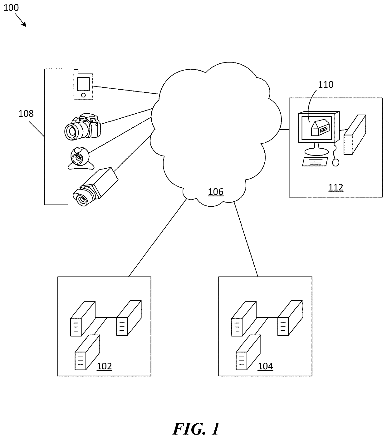
[0017]In various embodiments, a system provides for a platform for storing, accessing, displaying, manipulating, updating and editing various 3D model elements. 3D model elements, include, but are not limited to, 3D building models, with or without textures, and / or facade mapped surfaces (e.g., sides, roof, interior walls / surfaces, etc.). The 3D building model is representative of a physical building in the real-world. In some embodiments, a model generation system is provided that selects a 3D building model corresponding to a physical building in the real-world based on one or more uploaded images. An uploaded image is, for example, a photograph of a physical building. In other embodiments, the uploaded image includes a facade of the physical building. In alternative embodiments, the uploaded image is mapped as a facade of the building model.

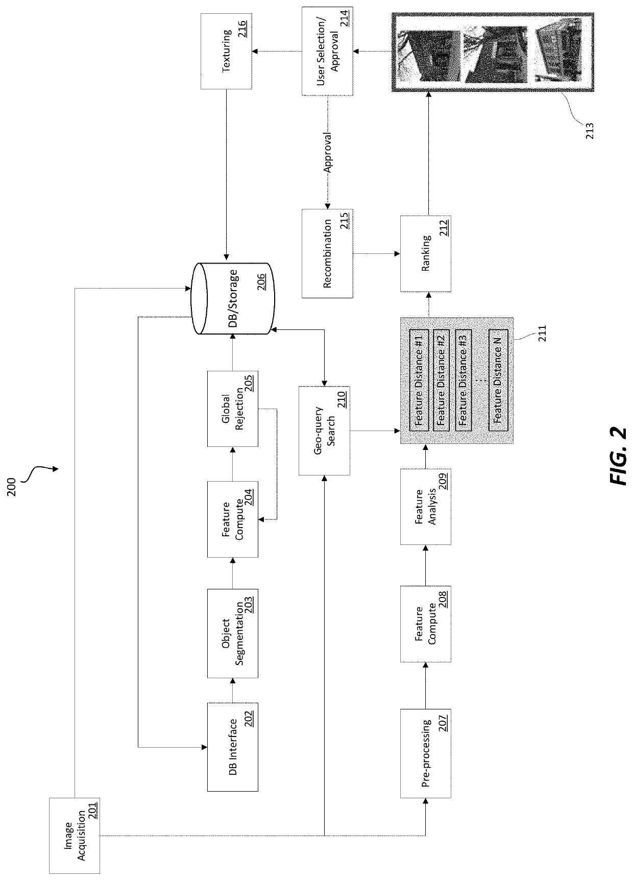
[0018]In one embodiment, the method of mapping an uploaded image to a building model includes: receiving an image and a geo-location tag of t...


PUM


Abstract

A system and method for real-time updating of three-dimensional (3D) building models includes receiving a request to analyze building imagery to detect potential physical changes in or around a first building, receiving the building imagery, the building imagery including one or more images of the building, optionally building a first 3D building model (textured or untextured) based on the building imagery, retrieving, from computer storage, a previously stored version of the first 3D building model, comparing, on a region-by-region basis, the first 3D building model against the previously stored version of the first 3D building model, cataloging in computer storage, based on the comparing, changes to the previously stored version of the first 3D building model, where the changes to the first 3D building model represent physical changes to or around the building occurring since a time of the previous stored version of the 3D building model.

Description

CROSS-REFERENCE TO RELATED APPLICATIONS / INCORPORATION BY REFERENCE[0001]The present Application is related to the following:[0002]1. U.S. Utility patent application Ser. No. 13 / 624,816, filed Sep. 21, 2012, entitled, “Three-Dimensional Map System”, now U.S. Pat. No. 8,878,865;[0003]2. U.S. Utility patent application Ser. No. 12 / 265,656, filed Nov. 5, 2008, entitled, “Method and System for Geometry Extraction, 3D Visualization and Analysis Using Arbitrary Oblique Imagery,” now U.S. Pat. No. 8,422,825; and 3. U.S. Utility patent application Ser. No. 14 / 303,126, filed Jun. 12, 2014, entitled “Computer Vision Database Platform for a Three-Dimensional Mapping System,” now U.S. Pat. No. 9,953,459.[0004]These applications are hereby incorporated herein by reference in their entirety and made part of the present Application for all purposes.BACKGROUNDTechnical Field[0005]This invention relates generally to a system and method for real-time updating of three-dimensional (3D) building models ...

Claims


Application Information

Patent Timeline
IPC IPC(8): G06T17/05G06T15/04G06T7/00G06T7/73
CPCG06T7/0002G06T2200/08G06T15/04G06T7/74G06T17/05G06F30/13G06T19/20G06T2219/2021G06Q40/08G06T2207/20081
Inventor UPENDRAN, MANISHCASTILLO, WILLIAMALTMAN, ADAM J.
Owner HOVER
Why Eureka
Try Eureka