Six-port self-injection-locked radar

Inactive Publication Date: 2020-10-29
SIL RADAR TECH INC
View PDF4 Cites 1 Cited by
  • Summary
  • Abstract
  • Description
  • Claims
  • Application Information

AI Technical Summary

Benefits of technology

[0003]The object of the present invention is to provide a six-port SIL radar which demodulates signals by using a six-port demodulation el

Problems solved by technology

However, the mixer unit of the receiver may be unavailable for higher operating frequen

Method used


Image

  • Six-port self-injection-locked radar
  • Six-port self-injection-locked radar
  • Six-port self-injection-locked radar

Examples


Embodiment Construction

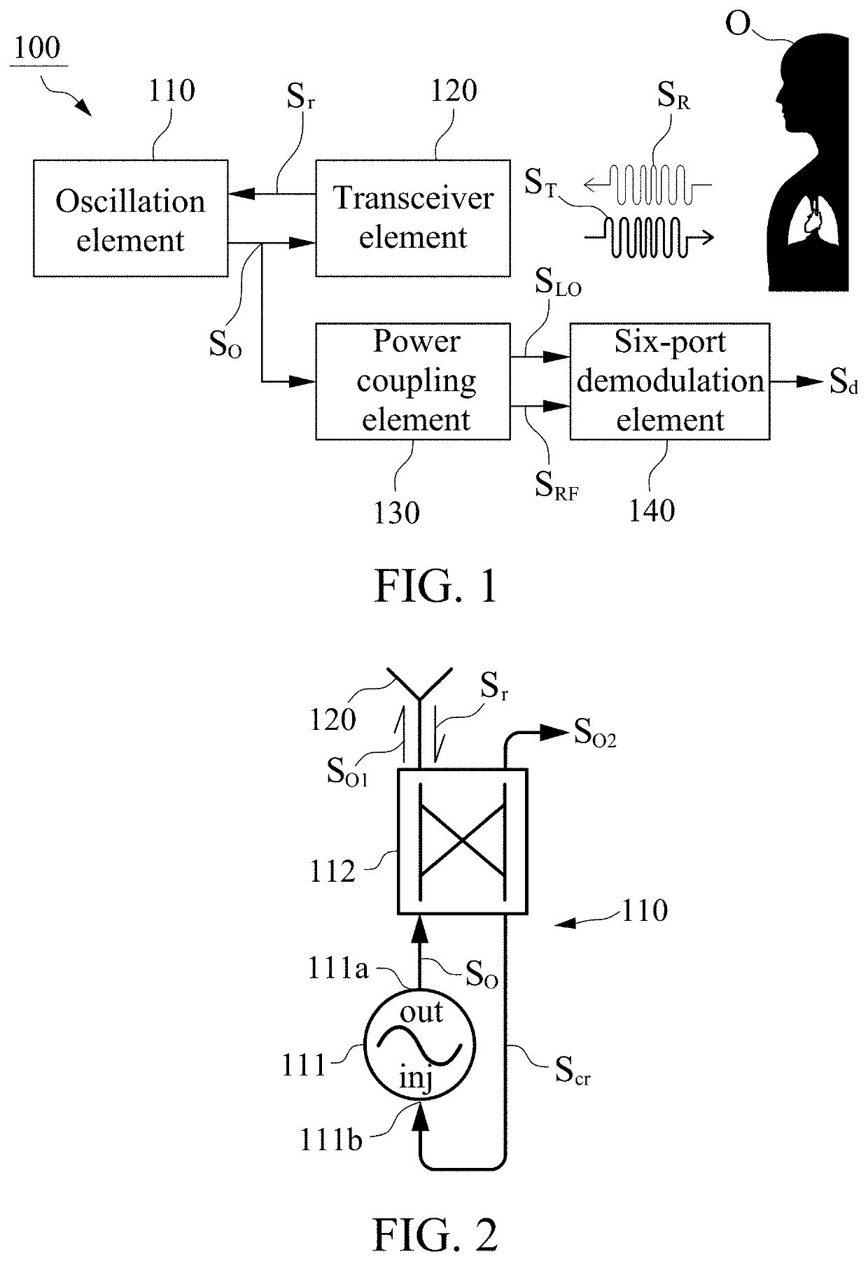
[0016]With reference to FIG. 1, a six-port SIL radar 100 in accordance with one embodiment of the present invention includes an oscillation element 110, a transceiver element 120, a power coupling element 130 and a six-port demodulation element 140. The oscillation element 110 outputs an oscillation signal SO, the transceiver element 120 is electrically connected to the oscillation element 110, transmits the oscillation signal SO as a transmitted signal ST to a subject O and receives a reflected signal SR from the subject O as a detection signal Sr, finally, the detection signal St is injected into the oscillation element 110 to form a SIL loop such that the oscillation element 110 operates in a SIL state. Based on the Doppler Effect, the reflected signal SR from the subject O and the detection signal Sr received by the transceiver element 120 contain the Doppler phase shifts caused by the movement of the subject O relative to the six-port SIL radar 100, and the detection signal Sr ...


PUM


Abstract

A six-port SIL radar includes an oscillation element, a transceiver element, a power coupling element and a six-port demodulation element. The six-port demodulation element is utilized to demodulate an oscillation signal from the oscillation element such that the operating frequency of the six-port SIL radar will not be restricted by hardware. Further, the power coupling element is configured to divide the oscillation signal into two signals that have equal power when received by the six-port demodulation element for signal-to-noise ratio optimization.

Description

FIELD OF THE INVENTION[0001]This invention generally relates to a self-injection-locked (SIL) radar, and more particularly to a six-port SIL radar.BACKGROUND OF THE INVENTION[0002]Taiwan Patent No. 1493213, entitled “Motion / interference signal detection system and method thereof”, discloses a motion / interference detection system which is a SIL radar. The motion / interference signal detection system is provided to transmit a wireless signal to an object and receive a reflected signal from the object by using a transmitter. The reflected signal is injected into the transmitter such that the motion / interference detection system enters a SIL state to modulate the wireless signal into a frequency-modulated signal, and at the same time, the wireless signal from the transmitter is also received by a receiver of the motion / interference detection system and demodulated to obtain a motion / interference signal of the object. FIGS. 4A, 4B and 4C of Taiwan Patent No. 1493213 show demodulation unit...

Claims


Application Information

Patent Timeline
IPC IPC(8): G01S7/35G01S13/34
CPCG01S13/34G01S7/35G01S7/021G01S7/414G01S7/03G01S7/354G01S13/536G01S13/88
Inventor WANG, FU-KANGLEE, CHAN-HUNGJUAN, PIN-HSUNTIAN, SHENG-YOU
Owner SIL RADAR TECH INC
Why Eureka
Try Eureka