Liquid crystal display apparatus

a liquid crystal display and display device technology, applied in the field of liquid crystal display devices, can solve the problems of increasing the frame width of the liquid crystal display apparatus, the waveform of the oscillatory potential is rounded, and the luminance error to be produced, so as to reduce the aperture ratio, increase the frame width, and reduce the display definition

Active Publication Date: 2020-10-29
SAKAI DISPLAY PROD
View PDF0 Cites 3 Cited by
  • Summary
  • Abstract
  • Description
  • Claims
  • Application Information

AI Technical Summary

Benefits of technology

[0010]The liquid crystal display apparatus being an Embodiment of the present disclosure can supply different oscillatory potentials (the first potential and the second potential) at a timing suitable for each of auxiliary capacita

Problems solved by technology

Therefore, an increase in the number of auxiliary capacitance trunk wirings causes an increase in the frame width of the liquid crystal display apparatus.
However, making the change in level of the oscillatory potential to occur in a short period increases load on the auxiliary capacitance wiring, causing rounding to occur in the waveform of the oscillatory potential.
Rounding occurring in the waveform of the oscillatory potential causes luminance errors to be produced in a sub-pixel, causing the display definition of the liquid crystal display apparatus to deteriorate.
However, light from a backlight is blocked in a region in which the auxiliary capacitance wiring is arranged,

Method used


Image

  • Liquid crystal display apparatus
  • Liquid crystal display apparatus
  • Liquid crystal display apparatus

Examples


embodiment 1

Configuration of Liquid Crystal Display Apparatus

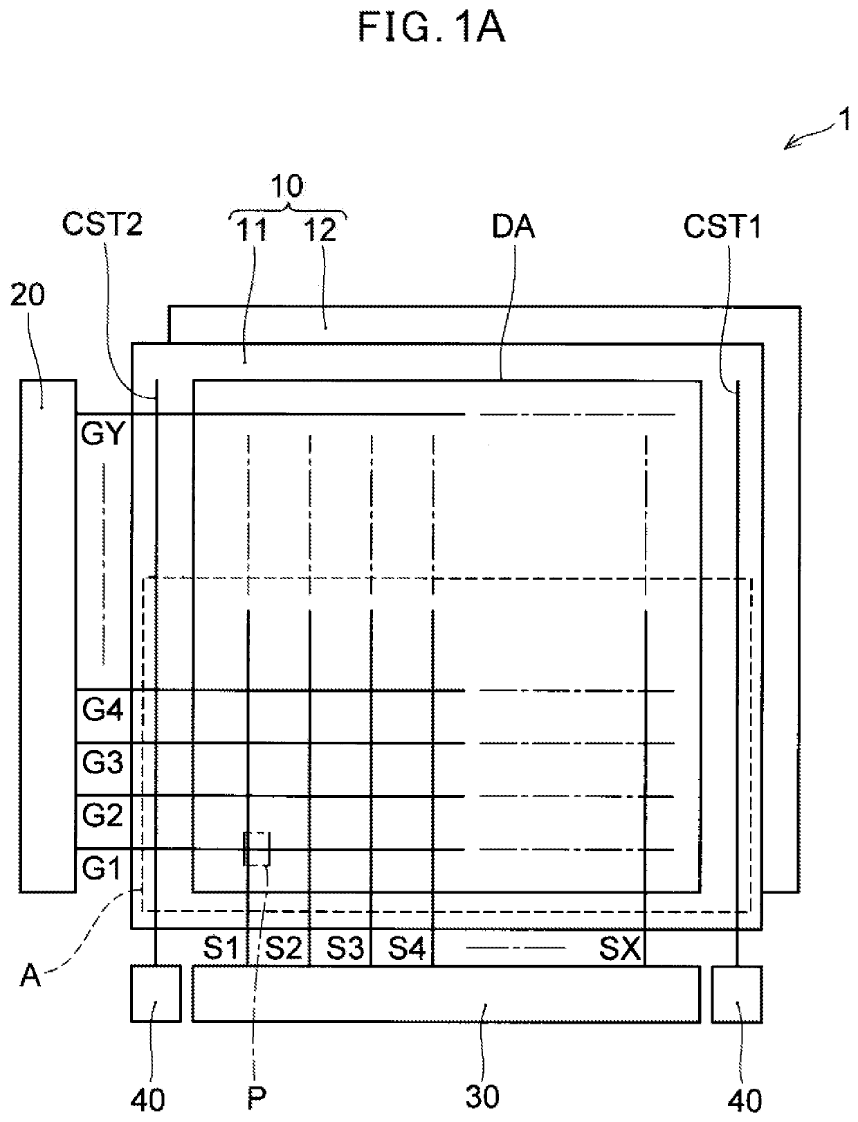
[0022]FIG. 1A schematically shows a block diagram of a configuration of a liquid crystal display apparatus according to Embodiment 1. In FIG. 1A, the liquid crystal display apparatus is viewed from a surface being opposite to a display surface to display an image. A liquid crystal display apparatus 1 according to the present Embodiment comprises a liquid crystal display panel 10, a scanning line drive unit 20, a data line drive unit 30, and an auxiliary capacitance line drive unit 40.

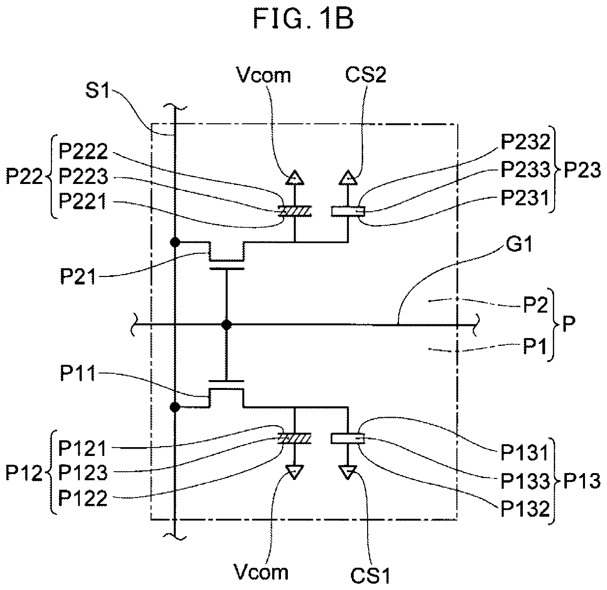
[0023]The liquid crystal display panel 10 comprises a pair of glass substrates 11 and 12, and liquid crystal layers P123, P223 (see FIG. 1B) being provided between the glass substrate 11 and the glass substrate 12.

[0024]The one glass substrate 11 comprises, in a display region DA of the liquid display panel 10, for example, a plurality of scanning lines G1 to GY extending in the row direction and being lined up in the column direction with the plurality o...

embodiment 2

[0068]Next, the liquid crystal display apparatus according to Embodiment 2 of the present disclosure will be explained. The liquid crystal display apparatus according to Embodiment 2 is different from the liquid crystal display apparatus according to Embodiment 1 with respect to arrangement of switching elements, auxiliary capacitance wirings, data lines, and data signals to be supplied. Therefore, the differing portions will be explained below.

Configuration of Liquid Crystal Display Apparatus According to Embodiment 2

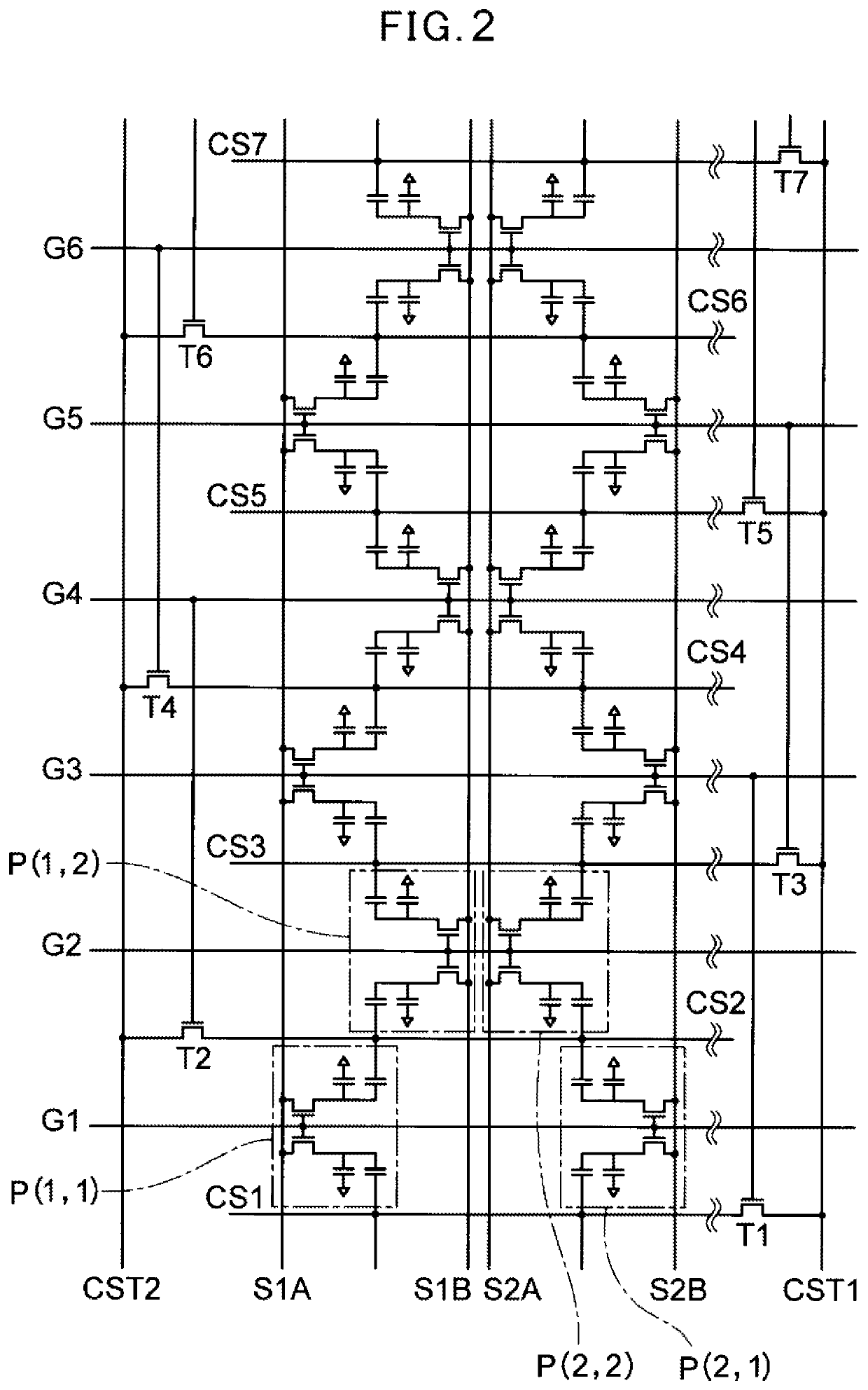
[0069]FIG. 5 is an equivalent circuit diagram to explain the liquid crystal display apparatus according to Embodiment 2 of the present disclosure, the equivalent circuit diagram showing the region shown with A in FIG. 1A as in FIG. 2. In the present Embodiment, a pixel P (m, n) comprises two sub-pixels being a first sub-pixel P1 and a second sub-pixel P2 in the same mariner as in the example shown in FIG. 1B. A first auxiliary capacitance P13 of the pixel P (m, n) and ...

embodiment 3

[0077]Next, the liquid crystal display apparatus according to Embodiment 3 of the present disclosure is explained. The liquid crystal display apparatus according to Embodiment 3 differs from the liquid crystal display apparatus according to Embodiment 2 in the arrangement of the auxiliary capacitance wirings and the switching elements to be connected thereto. Therefore, the differing portions will be explained below.

Configuration of Liquid Crystal Display Apparatus According to Embodiment 3

[0078]FIG. 8 shows an equivalent circuit diagram to explain the display apparatus according to Embodiment 3 of the present disclosure. In the same manner as in FIG. 2 and FIG. 5, the region shown with A in FIG. 1 is shown. In the present Embodiment, the difference from Embodiment 2 is in that agate electrode of a switching element TnB in which the drain electrode is connected to an auxiliary capacitance wiring CSnB is connected to a scanning line Gn+2 being two rows following a scanning line Gn to...


PUM


Abstract

A liquid crystal display apparatus is disclosed. In the liquid crystal display apparatus, a first pixel of a plurality of pixels arranged in a matrix comprises a first sub-pixel and a second sub-pixel. The first sub-pixel and the second sub-pixel are connected to a first scanning line of a plurality of scanning lines, to which the first scanning line is supplied a first scanning signal. A first potential is supplied to a first auxiliary capacitance of the first sub-pixel based on a first control signal to select any of a plurality of row pixel groups after the first scanning signal. A second potential being different from the first potential is supplied to a second auxiliary capacitance of the second sub-pixel based on a second control signal to select any one of a plurality of row pixel groups after the first scanning signal.

Description

CROSS-REFERENCE TO RELATED APPLICATIONS[0001]This application claims priority to and the benefit of priority of U.S. Provisional Application No. 62 / 838,497, filed on Apr. 25, 2019, the entire contents of which are incorporated herein by reference.BACKGROUNDTechnical Field[0002]The present disclosure relates to a liquid crystal display apparatus.Description of Related Art[0003]In the liquid crystal display apparatus, a pixel division scheme can be adopted to make an improvement on the problem of viewing angle dependency in which how a screen is viewed varies with viewing directions. In the pixel division scheme, each of a plurality of pixels being arranged in a matrix is divided into a plurality of sub-pixels. In the plurality of sub-pixels in the same pixel, alignment directions of liquid crystal molecules are controlled such that they are different from one another.[0004]WO2006 / 098449 discloses a liquid crystal display apparatus using the pixel division scheme in which a plurality ...

Claims


Application Information

Patent Timeline
IPC IPC(8): G09G3/36
CPCG09G3/3648G09G3/3674G09G3/3614G09G2300/0439G09G3/3685G02F1/136213G02F1/1368G09G3/3655G09G3/3666G09G2300/0876G09G2310/0218
Inventor HASEGAWA, KOJIOKUMOTO, YOSHITAKAAWA, TOKUYOSHI
Owner SAKAI DISPLAY PROD
Why Eureka
Try Eureka