
Nurse call system

a call system and call system technology, applied in the field of nurse call system, can solve the problems of increasing hospitalized patients cannot know when the nurse performs nursing rounds, and the nurse does not perform nursing rounds at the exact fixed time, so as to facilitate the input of nursing records and reduce the load of nursing work on nurses

Pending Publication Date: 2020-10-29
AIPHONE CO LTD
View PDF4 Cites 4 Cited by
  • Summary
  • Abstract
  • Description
  • Claims
  • Application Information

AI Technical Summary

Benefits of technology

The present invention is a nurse call system that improves the efficiency of nursing work by allowing hospitalized patients to know when their assigned nurse has started rounds. The system also reduces the strain on nurses by not necessarily needing them to answer a master device for all calls and allows patients to measure vital signs on their own. It also allows nurses to confirm the state of hospitalized patients without visiting the hospital room. Additionally, the system helps input nursing records, which simplifies the process of caring for patients.

Problems solved by technology

However, the nurse does not perform nursing rounds at the exact fixed time every day.
Therefore, the hospitalized patients cannot know when the nurse performs nursing rounds, and the hospitalized patient may be absent when the nurse visits the hospital room in the nursing rounds.
When the hospitalized patient is absent, the nurse needs to visit the hospital room of the hospitalized patient later again for the nursing rounds, thereby increasing load of the nursing work.
The nurse needs to answer each call from the nurse call slave device regardless of the content, thereby increasing load of the nursing work.
When the hospitalized patient is absent, the nurse needs to visit the hospital room again, so that it takes a long time to complete the nursing rounds, thereby increasing load of the nursing work.
In a case where a nurse is assigned to many hospitalized patients, a very long time is required for completing the nursing rounds, and the nursing rounds to be performed several times a day increase a load of their nursing work.
Therefore, the load cannot be substantially reduced.

Method used


Image

  • Nurse call system
  • Nurse call system
  • Nurse call system

Examples


first embodiment

[0107]the present invention is described below.

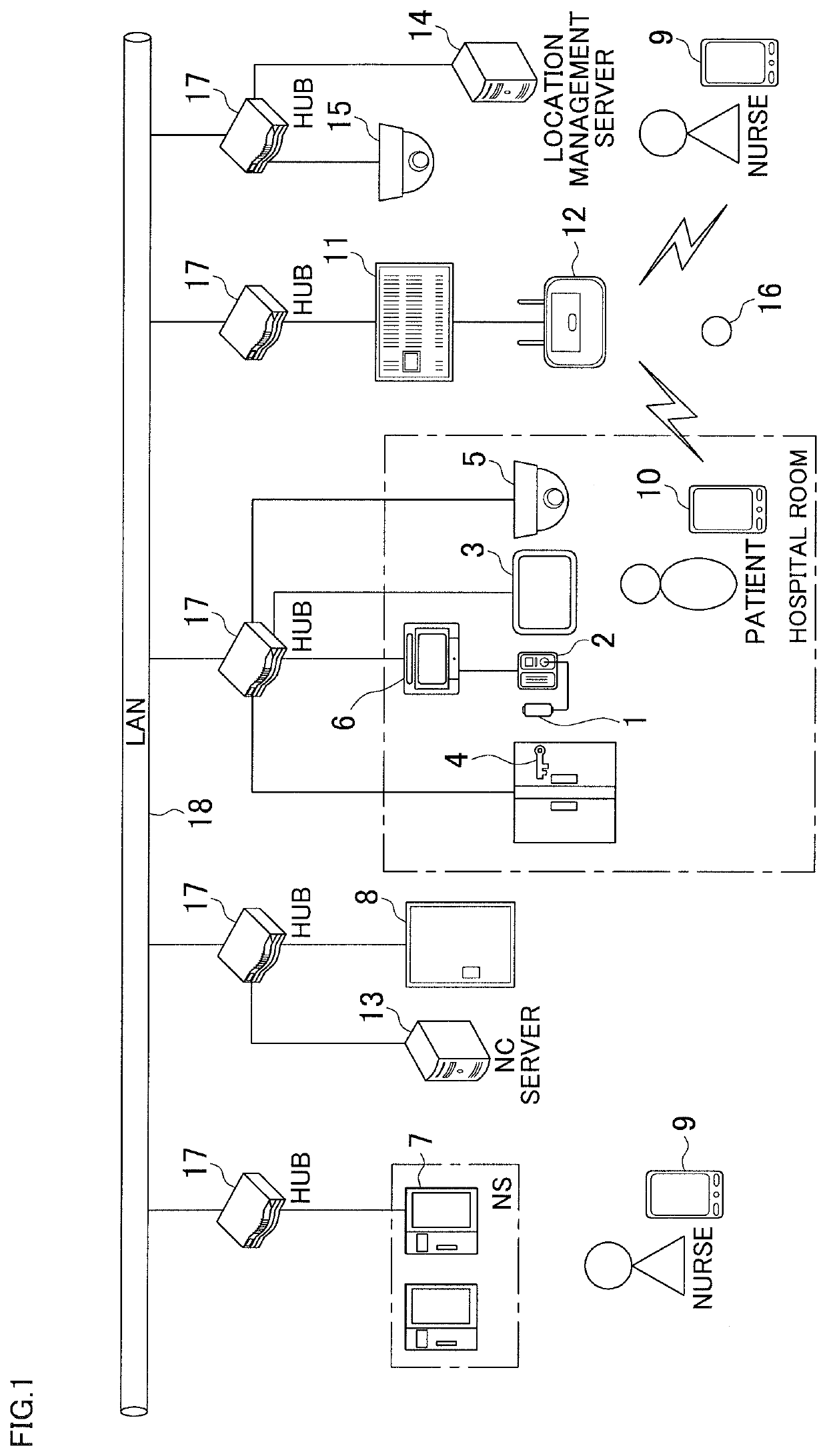
[0108]FIG. 1 illustrates a configuration of a nurse call system according to the first embodiment of the present invention.

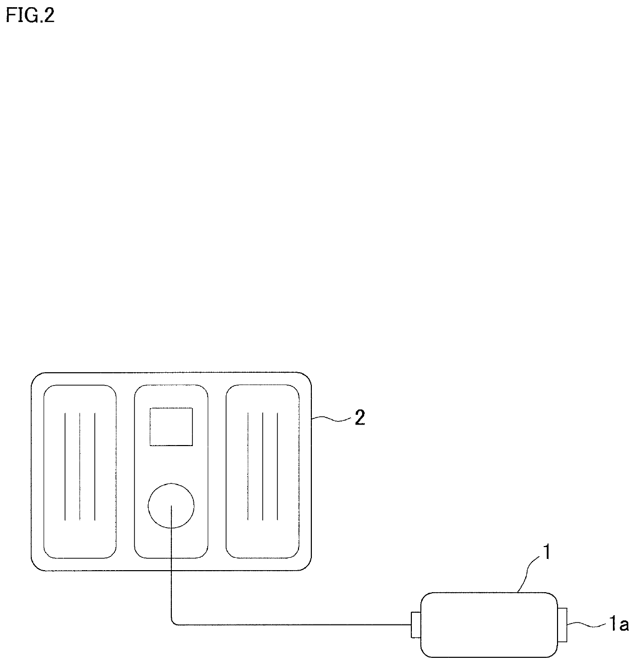
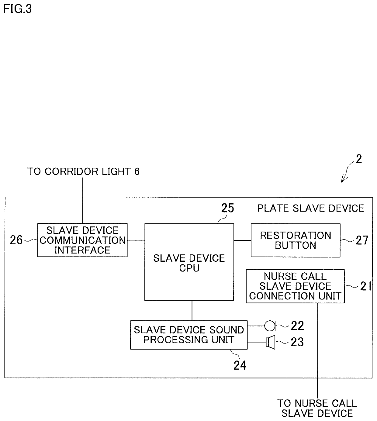
[0109]As shown in FIG. 1, the nurse call system includes a nurse call slave device 1, a plate slave device 2, a bedside monitor 3, an electronic key 4, a hospital room camera 5, a corridor light 6, a nurse call master device 7, a controller 8, a nurse mobile phone 9, and a hospitalized patient mobile phone 10. The nurse call slave device 1 is provided for each bed in a hospital room for allowing a hospitalized patient to call a nurse. To the plate slave device 2, the nurse call slave device 1 is connected, and the plate slave device 2 is provided on a wall surface near the bed in the hospital room. The bedside monitor 3 is provided for each bed in the hospital room and is capable of displaying patient-related information. The electronic key 4 is disposed at a door of the hospital room. The hospital room camera 5 is ...

second embodiment

[0174]the present invention is described below.

[0175]A nurse call system according to the second embodiment of the present invention has the entire configuration that includes the nurse call slave device 1, the plate slave device 2, the bedside monitor 3, the electronic key 4, the hospital room camera 5, the corridor light 6, the nurse call master device 7, the controller 8, the nurse mobile phone 9, the hospitalized patient mobile phone 10, the IP-PBX 11, the nurse call server 13, the location management server 14, the common area camera 15, and the IMES transmitter 16, similarly to the nurse call system according to the first embodiment.

[0176]Meanwhile, the controller 8 of the present embodiment includes an automatic answering unit 174 in addition to the information storage unit 71 for storing various information, the controller CPU 72, and the controller communication IF 73, as shown in FIG. 11.

[0177]The automatic answering unit 174 includes a keyword storage unit 174a for storin...

third embodiment

[0222]the present invention is described below.

[0223]A nurse call system according to the third embodiment of the present invention has the entire configuration that includes the nurse call slave device 1, the plate slave device 2, the bedside monitor 3, the electronic key 4, the hospital room camera 5, the corridor light 6, the nurse call master device 7, the controller 8, the nurse mobile phone 9, the hospitalized patient mobile phone 10, the IP-PBX 11, the nurse call server 13, the location management server 14, the common area camera 15, and the IMES transmitter 16, similarly to the nurse call system according to the first embodiment.

[0224]Meanwhile, the bedside monitor 3 of the present embodiment includes a vital sign obtaining unit 240, in addition to the monitor 31, the side monitor video processing unit 32, the operation unit 33, the microphone 34 and the loudspeaker 35, the side monitor sound processing unit 36, the side monitor CPU 37, the side monitor communication IF 38,...


PUM


Abstract

A nurse call system includes a nurse call slave device, a nurse call master device, a plate slave device, a bedside monitor, a corridor light, a control unit, and nurse mobile phones. The nurse call slave device is provided for each bed in a hospital room for allowing a hospitalized patient to call a nurse. The nurse call master device is provided at a nurse station for answering a call from the nurse call slave device. The plate slave device, the corridor light, or the control unit has an automatic answering unit for automatically answering a call from the nurse call slave device, and causes the automatic answering unit to automatically answer at least a part of calls from the nurse call slave device without calling the nurse call master device and the nurse mobile phones.

Description

BACKGROUND OF THE INVENTION[0001]This application is a Continuation of International Application No. PCT / JP2018 / 015902 filed on Apr. 17, 2018, which claims the benefit of the Japanese Patent Application No. 2018-005122 filed on Jan. 16, 2018, No. 2018-017514 filed on Feb. 2, 2018, No. 2018-031147 filed on Feb. 23, 2018, No. 2018-034650 filed on Feb. 28, 2018, and No. 2018-051337 filed on March 19, 2018, the disclosures of which are incorporated by reference herein in their entireties.FIELD OF THE INVENTION[0002]The present invention relates to a nurse call system.DESCRIPTION OF RELATED ART[0003]Conventionally, a nurse call system in which, when a call is made using a nurse call slave device provided to an individual bed, a nurse call master device provided at a nurse station, or the like is notified of the call, has been widespread. In such a nurse call system, a bed number and a name of a patient who has made the call is displayed on a display unit in the called nurse call master d...

Claims


Application Information

Patent Timeline
Patent Type & Authority Applications(United States)
IPC IPC(8): G16H40/20G16H40/63G10L15/08H04W4/029H04W84/20
CPCH04W84/20H04W4/029G10L2015/088G16H40/20G16H40/63G10L15/08H04M9/00H04M11/00H04N7/18A61B5/00A61G12/00G08B25/04H04M9/02G16H40/67H04W4/02H04W4/90H04W4/33A61B5/0015A61B5/0002A61B5/002
Inventor OGAWA, KENICHI
Owner AIPHONE CO LTD
Learn More