Eureka AIR delivers breakthrough ideas for toughest innovation challenges, trusted by R&D personnel around the world.

System and method for establishing a device to device communication link in cellular networks

a communication link and cellular network technology, applied in the field of cellular networks, can solve the problems of huge cellular network entry delay and inability to provide critical services, and achieve the effect of reducing the number of devices

Active Publication Date: 2020-10-29
SAANKHYA LABS PVT
View PDF0 Cites 1 Cited by
  • Summary
  • Abstract
  • Description
  • Claims
  • Application Information

AI Technical Summary

Benefits of technology

[0005]In view of the foregoing, a system for establishing a device to device communication link in cellular networks using a transmit to receive transition gap (TTG) and a receive to transmit transition gap (RTG) of the cellular networks is provided. The system includes a base station, one or more user equipments, a memory and a storage device, and a processor. The base station is coupled to a cellular tower. The one or more user equipments includes a first user equipment and a second user equipment. The first user equipment is configured with a first user equipment cognitive engine and the second user equipment is configured with a second user equipment cognitive engine. In an embodiment, the processor in communication with the memory and the storage device, the processor executing machine readable program instructions for performing a method for establishing the device to device communication link in the cellular networks using the TTG (transmit to receive transition gap) and the RTG (receive to transmit transition gap). The method includes performing a time synchronization through at least one of (i) a downlink reference signal from the base station, (ii) a GPS (Global Positioning System) timing signal, or (iii) a timing reference signal from a digital television DTV, scheduling a downlink bandwidth for the first user equipment at the starting of a downlink transmission interval. The downlink transmission interval includes radio frames. The radio frames are divided into n sub frames of equal time interval based on a configuration of the cellular networks. The starting of the downlink transmission interval is a starting of a sub frame one and scheduling an uplink bandwidth for the first user equipment at an end of an uplink transmission interval to reduce the probability of overlapping signals at the TTG. The uplink transmission interval includes radio frames. The radio frames are divided into n sub frames of equal time interval based on a configuration of the cellular networks. The end of the uplink transmission interval is an end of a sub frame n. The one or more user equipments establishes the device to device communication link in a TTG timing interval or a RTG timing interval.
[0011]In some embodiments, the system includes a method for increasing a number of active users served by the base station by establishing the device to device communication between the one or more user equipments. The method includes searching for the first user equipment presence which is connected to the base station; and establishing the device to device communication link with the first user equipment by the second user equipment on finding the first user equipment presence.
[0020]In some embodiments, a method for increasing a number of active users served by the base station by establishing the device to device communication between the one or more user equipments is provided. The method includes (i) searching for the first user equipment presence which is connected to the base station; and (ii) establishing the device to device communication link with the first user equipment by the second user equipment on finding the first user equipment presence.

Problems solved by technology

Such fixed parameters might not be suitable for highly dense cellular networks resulting in RACH back offs which leads to huge cellular network entry delays.
Delays in entering the cellular network are not acceptable in critical services.

Method used


Image

  • System and method for establishing a device to device communication link in cellular networks
  • System and method for establishing a device to device communication link in cellular networks
  • System and method for establishing a device to device communication link in cellular networks

Examples


Embodiment Construction

[0038]The embodiments herein and the various features and advantageous details thereof are explained more fully with reference to the non-limiting embodiments that are illustrated in the accompanying drawings and detailed in the following description. Descriptions of well-known components and processing techniques are omitted so as to not unnecessarily obscure the embodiments herein. The examples used herein are intended merely to facilitate an understanding of ways in which the embodiments herein may be practiced and to further enable those of skill in the art to practice the embodiments herein. Accordingly, the examples should not be construed as limiting the scope of the embodiments herein.

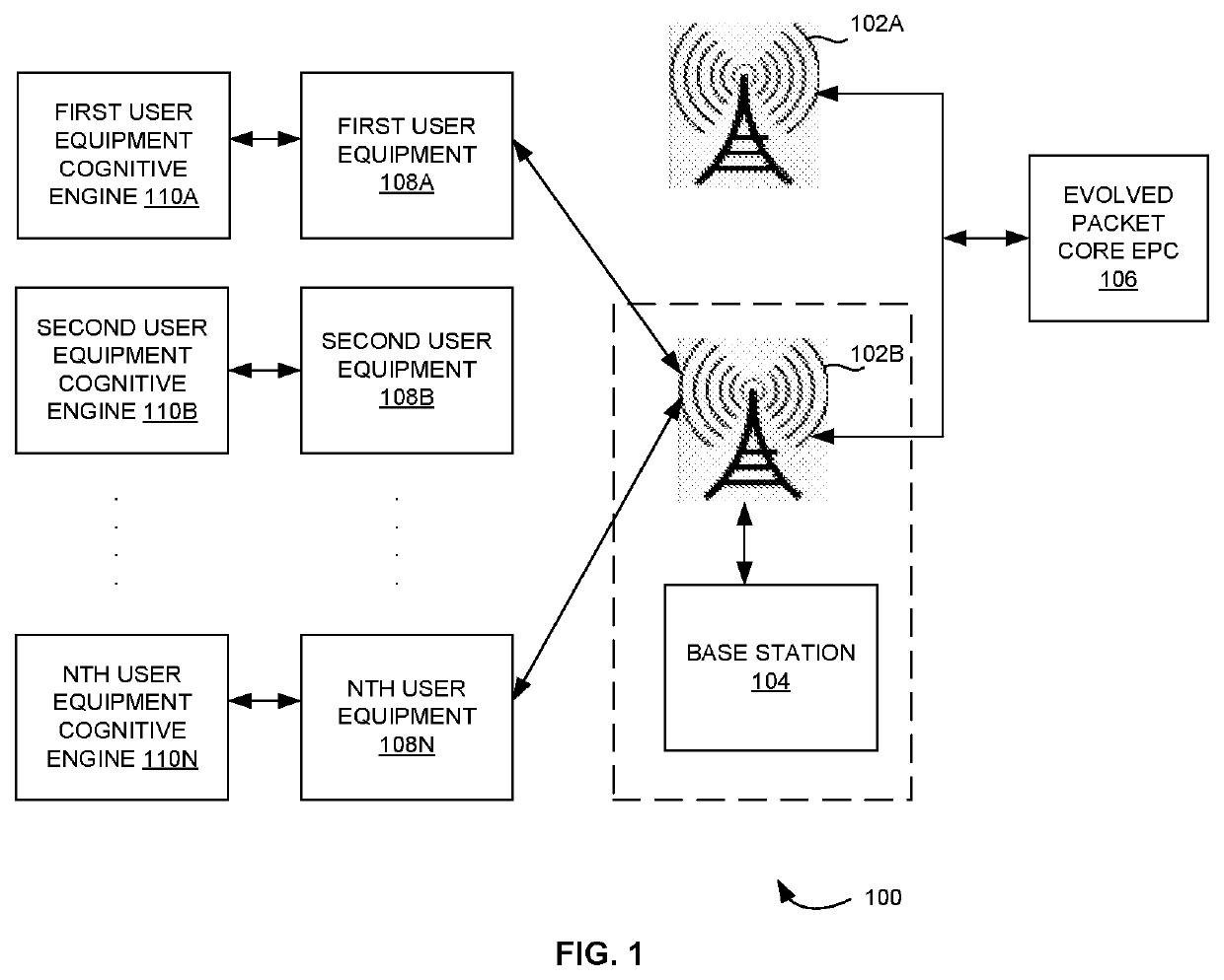
[0039]As mentioned, there remains a system and method for establishing a device to device communication link in cellular networks. The embodiments herein achieve this by configuring a cognitive engine on a User Equipment (UE) which gathers data from multiple sources for achieving an optimized p...


PUM


Abstract

Disclosed is a system and method for establishing a device to device communication link in cellular networks. The system includes one or more user equipments, and a base station. The one or more user equipments includes a first user equipment and a second user equipment. The first user equipment is configured with a first user equipment cognitive engine and the second user equipment is configured with a second user equipment engine. The base station that is coupled to a cellular tower and configured with an evolved packet core EPC. The base station and at least one of the one or more user equipments performs a method for establishing the device to device communication link in the cellular network using a transmit to receive transition gap (TTG) and a receive to transmit transition gap (RTG).

Description

CROSS-REFERENCE TO RELATED APPLICATIONS[0001]This application claims priority to Indian patent application no. 201941016744 filed on Apr. 26, 2019, the complete disclosure of which, in its entirely, is herein incorporated by reference.BACKGROUNDTechnical Field[0002]The embodiments herein generally relate to cellular networks, and more particularly, to a system and method for establishing a device to device communication link in the cellular networks.Description of the Related Art[0003]Currently in cellular network deployment, a base station is configured once during deployment and most parameters related to random-access channel (RACH) are fixed during such configuration. Such fixed parameters might not be suitable for highly dense cellular networks resulting in RACH back offs which leads to huge cellular network entry delays. Delays in entering the cellular network are not acceptable in critical services.[0004]Accordingly, there remains a need for a system and method for establishi...

Claims


Application Information

Patent Timeline
Patent Type & Authority Applications(United States)
IPC IPC(8): H04W76/10H04W72/04H04W56/00
CPCH04W72/04H04W76/10H04W56/001H04W76/28H04W74/0833H04W72/23
Inventor PADAKI, GURURAJKAYARGADDE, VISHWAKUMARA KAYARGADDEHEGDE, RAJENDRA V.HULLENAHALLI, ANOOP
Owner SAANKHYA LABS PVT
Why Eureka
Eureka Blog
Learn More