Bi-conical optical sensor for obtaining downhole fluid properties

Active Publication Date: 2020-11-12
BAKER HUGHES OILFIELD OPERATIONS LLC
View PDF0 Cites 0 Cited by
  • Summary
  • Abstract
  • Description
  • Claims
  • Application Information

AI Technical Summary

Benefits of technology

The present patent describes a system and method for analyzing the properties of fluids in a well. The system includes an optical sensor with a bi-conical tip that emits light and receives the light returned through internal reflection. The optical tip has a first conical portion and a second conical portion, and the light emitted has different wavelengths that are attenuated by the presence of different fluids. The system can identify the presence of oil and water in the fluid sample. The method involves emitting light into the optical tip, receiving the returned light, and analyzing the spectral content to determine the fluid types. The technical effect of this patent is to provide a more accurate and reliable way to analyze the properties of fluids in a well.

Problems solved by technology

During oil and gas operations, it is often difficult to determine fluid properties in a downhole well due to inaccessibility, contamination of fluids, mixing of fluids, and the like.
These tools are often fragile, and as a result, may not be utilized in multiple operations.
Furthermore, installing multiple tools along a drill or wireline string increases costs of the operation and also may lead to slower drilling and or wireline logging operations because some tools are individually tripped into and out of the well.
In additional, current techniques are incapable of performing true multi-phase fluid metering.
Therefore, conventional absorption spectroscopy may be difficult for analyzing dark or opaque samples or for highly scattering fluids that contain suspended particles such as sand or which contain small bubbles of one immiscible phase within another such as emulsions.

Method used


Image

  • Bi-conical optical sensor for obtaining downhole fluid properties
  • Bi-conical optical sensor for obtaining downhole fluid properties
  • Bi-conical optical sensor for obtaining downhole fluid properties

Examples


Embodiment Construction

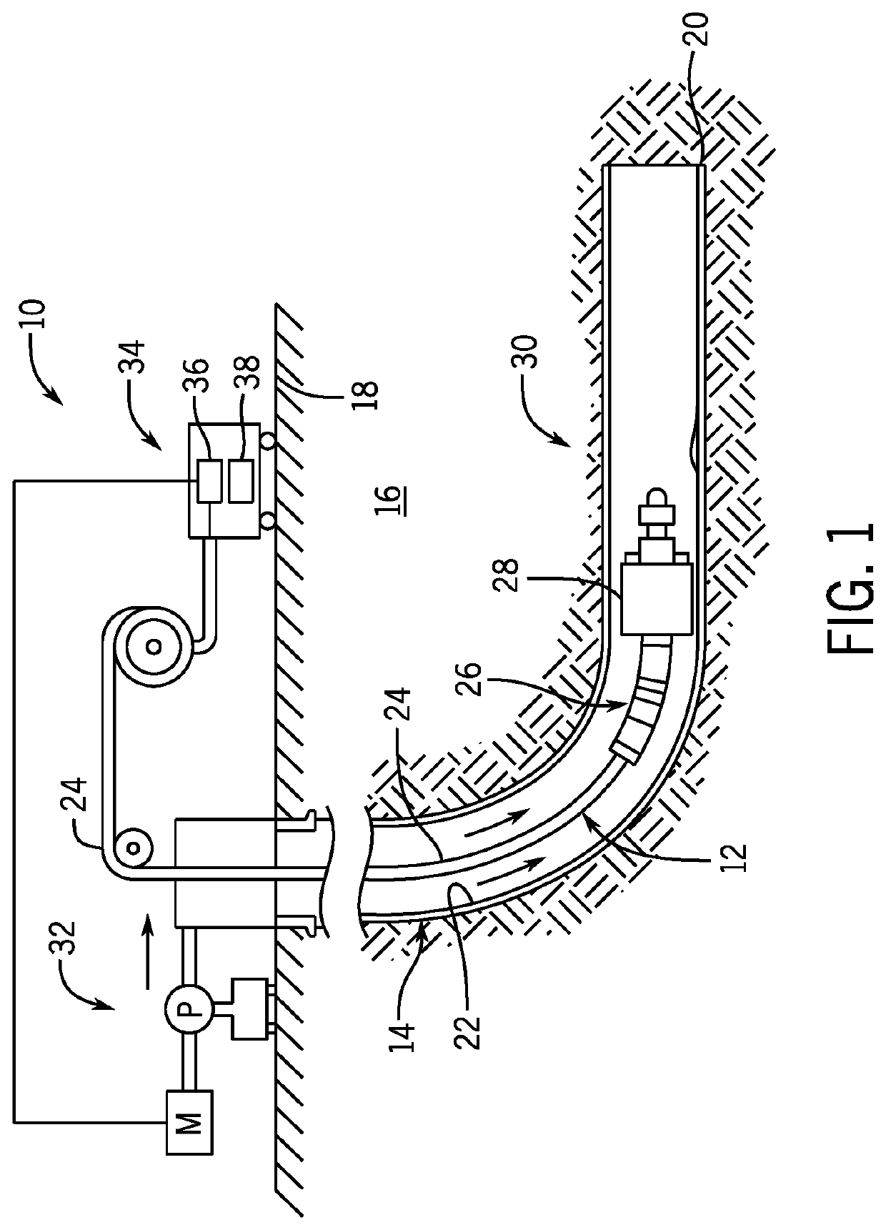
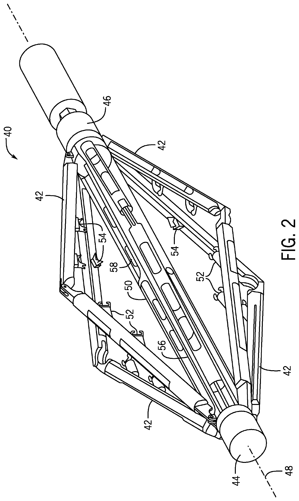
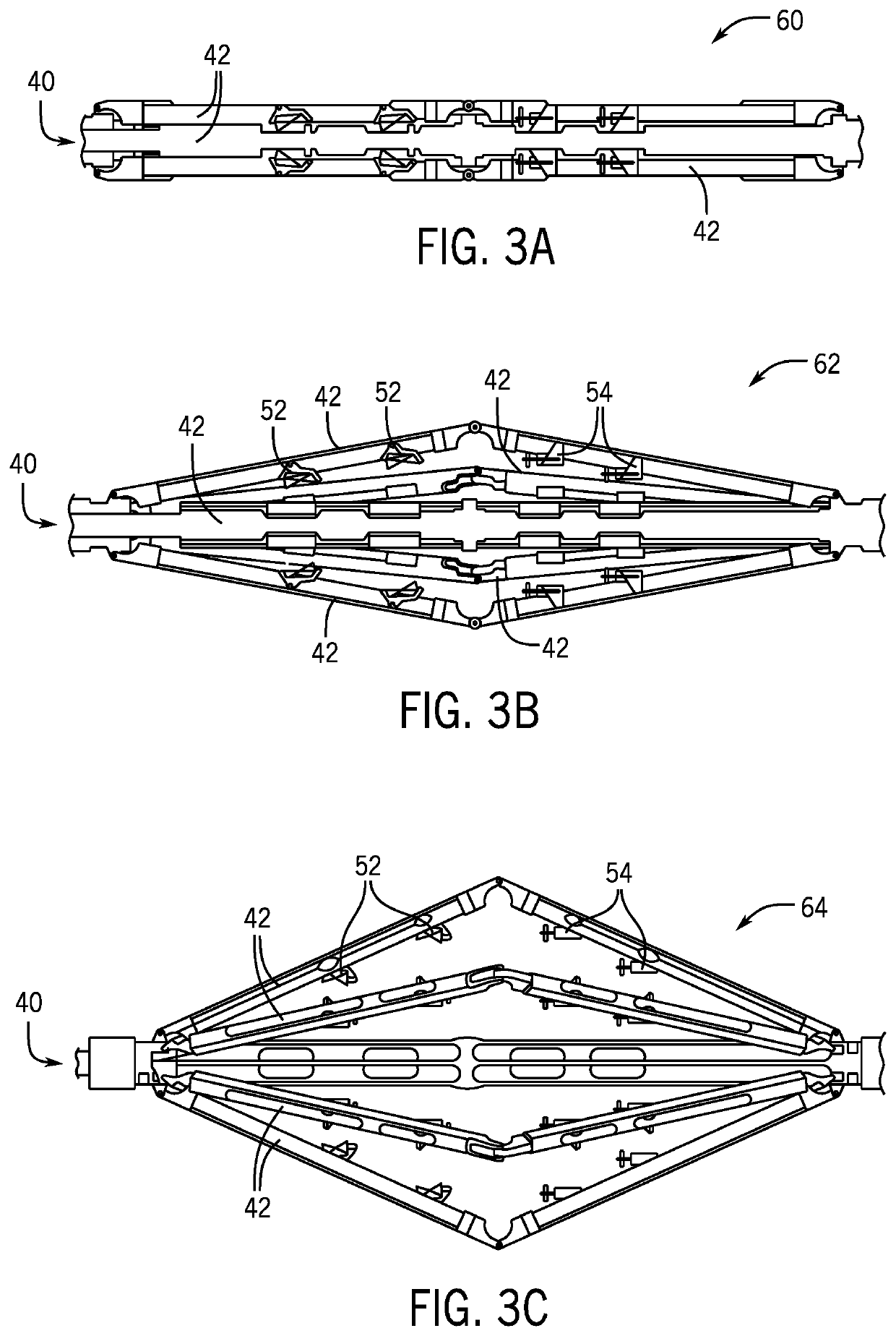
[0028]The foregoing aspects, features, and advantages of the present disclosure will be further appreciated when considered with reference to the following description of embodiments and accompanying drawings. In describing the embodiments of the disclosure illustrated in the appended drawings, specific terminology will be used for the sake of clarity. However, the disclosure is not intended to be limited to the specific terms used, and it is to be understood that each specific term includes equivalents that operate in a similar manner to accomplish a similar purpose.

[0029]When introducing elements of various embodiments of the present disclosure, the articles “a”, “an”, “the”, and “said” are intended to mean that there are one or more of the elements. The terms “comprising”, “including”, and “having” are intended to be inclusive and mean that there may be additional elements other than the listed elements. Any examples of operating parameters and / or environmental conditions are not...


PUM


Abstract

A downhole fluid analysis system includes an optical sensor that includes a light source configured to emit light, a light detector, and an optical tip optically coupled to the light source and the light detector. At least a portion of the light emitted from the light source travels through the optical tip and returns to the detector, wherein the optical tip has a bi-conical shape. The system further includes a piezoelectric helm resonator, in which the piezoelectric helm resonator generates a resonance response in response to an applied current, and an electromagnetic spectroscopy sensor positioned symmetrically with respect to the piezoelectric helm resonator in at least one direction. In some embodiments, the optical tip includes a first conical portion and a second conical portion.

Description

CROSS REFERENCE TO RELATED APPLICATIONS[0001]This application claim priority to U.S. Patent Application No. 62 / 846,012 filed May 10, 2019 titled “SYSTEMS AND METHODS FOR OPTICAL DETECTION OF MULTI-PHASE FLUID,” the disclosure of which is incorporated herein by reference in its entirety.BACKGROUND1. Field of the Invention[0002]The present disclosure relates to downhole measurements. More particularly, the present disclosure relates to obtaining a number of properties of the fluid inside a wellbore.2. Description of Related Art[0003]During oil and gas operations, it is often difficult to determine fluid properties in a downhole well due to inaccessibility, contamination of fluids, mixing of fluids, and the like. As a result, typical operations deploy multiple tools that may be specialized to determine a single fluid property, such as density. These tools are often fragile, and as a result, may not be utilized in multiple operations. Furthermore, installing multiple tools along a drill...

Claims


Application Information

Patent Timeline
IPC IPC(8): E21B49/08E21B47/113
CPCE21B49/081E21B47/113G01N21/64G01N21/09G01N21/8507G01N2021/855G01N21/552E21B47/00G01F1/661E21B47/135
Inventor MAITY, SANDIP
Owner BAKER HUGHES OILFIELD OPERATIONS LLC
Why Eureka
Try Eureka