3D printed luminaires using optical fibers

a technology of optical fibers and luminaires, applied in the direction of additive manufacturing processes, lighting and heating apparatus, instruments, etc., can solve the problems of relatively low thermal conductivity and poor stability of photocurable materials to be useful for injection molding applications

Active Publication Date: 2019-10-22
SIGNIFY HLDG BV
View PDF15 Cites 0 Cited by
  • Summary
  • Abstract
  • Description
  • Claims
  • Application Information

AI Technical Summary

Benefits of technology

[0006]FDM printers are relatively fast, low cost and can be used for printing complicated 3D objects. Such printers are used in printing various shapes using various polymers. The technique is also being further developed in the production of LED luminaries and lighting solutions.
[0009]With such method, it is possible to provide a 3D printed device that allows lighting spots or lighting areas at predefined positions of the 3D printed item where the dimensions and positions of the lighting spots or lighting areas may be chosen with a relative large freedom of choice, e.g. for decorative light or functional lighting, for providing signs, etc. It may also be that essentially the entire 3D printed item may be light emitting, due to the fact that the invention allows a good distribution of the light in the 3D printed item. With the present invention, it is possible to provide 3D printed luminaries (also) using optical fibers.
[0034]In embodiments, during the printing stage the light escape part is further provided by configuring the optical fiber with a bending angle (a) that facilitates light escape from the optical fiber. Hence, the method may (thus) comprise depositing the optical fiber with a curvature which promotes outcoupling of visible light at the curvature, wherein the curvature of the optical fiber in the 3D printed material is comprised by the light escape part. With optical fibers having a diameter, including optional cladding, of equal to or less than about 400 μm, curvatures can be made that reduce locally total internal reflection. Especially, the angle α defines an arc, with a being at least 45°, especially in the range of 45°-135°, and with the concomitant radius of the arc being at maximum about 1 cm. In embodiments, the optical fiber may be provided with a bending having a bending radius which is especially at maximum 20 times the diameter, such as at maximum 15 times the diameter of the optical fiber, like especially at maximum 10 times the diameter of the optical fiber, such as at maximum 5 times the diameter of the optical fiber.
[0038]As indicated above, the cladding may have in general an index of refraction lower than the core. This facilitates total internal reflection in the optical fiber. By choosing light transmissive material having an index of refraction larger than the optical fiber, outcoupling may be facilitate, especially when no cladding is available (over part of the length of the optical fiber). Hence, in embodiments the light transmissive material comprised by the light escape part has an index of refraction higher than an index of refraction of the optical fiber (wherein at least part of the optical fiber in contact with the light transmissive material does not comprise a cladding). The light transmissive material may have an index of refraction larger than of the core, such as at least 5% larger, like at least 20% larger.
[0046]Hence, in specific embodiment one or more of (i) the optical fiber within the light escape part has a bending angle and / or radius (a) that facilitates light escape from the optical fiber, (ii) the optical fiber within the light escape part has an outcoupling feature for facilitating light escape from the optical fiber via the outcoupling feature, and (iii) the light transmissive material comprised by the light escape part has an index of refraction higher than an index of refraction of the optical fiber.
[0049]In further embodiments, one or more of (i) the optical fiber comprises a core comprising a glass material and a cladding, wherein at least part of the core is not covered by the cladding wherein the part is at least partly comprised by the light escape part, and (ii) the optical fiber comprises an outcoupling feature comprising a defect for facilitating outcoupling of visible light from the optical fiber, wherein at least part of the outcoupling feature is comprised by the light escape part. In this way, outcoupling from the optical fiber of one or more of UV, visible, and IR radiation, especially visible, when provided to the optical fiber with a light source functionally coupled to the fiber, may (further) be facilitated.

Problems solved by technology

While this technique produces smooth surfaces the photo curable materials are not very stable and they also have relatively low thermal conductivity to be useful for injection molding applications.

Method used


Image

  • 3D printed luminaires using optical fibers
  • 3D printed luminaires using optical fibers
  • 3D printed luminaires using optical fibers

Examples


Embodiment Construction

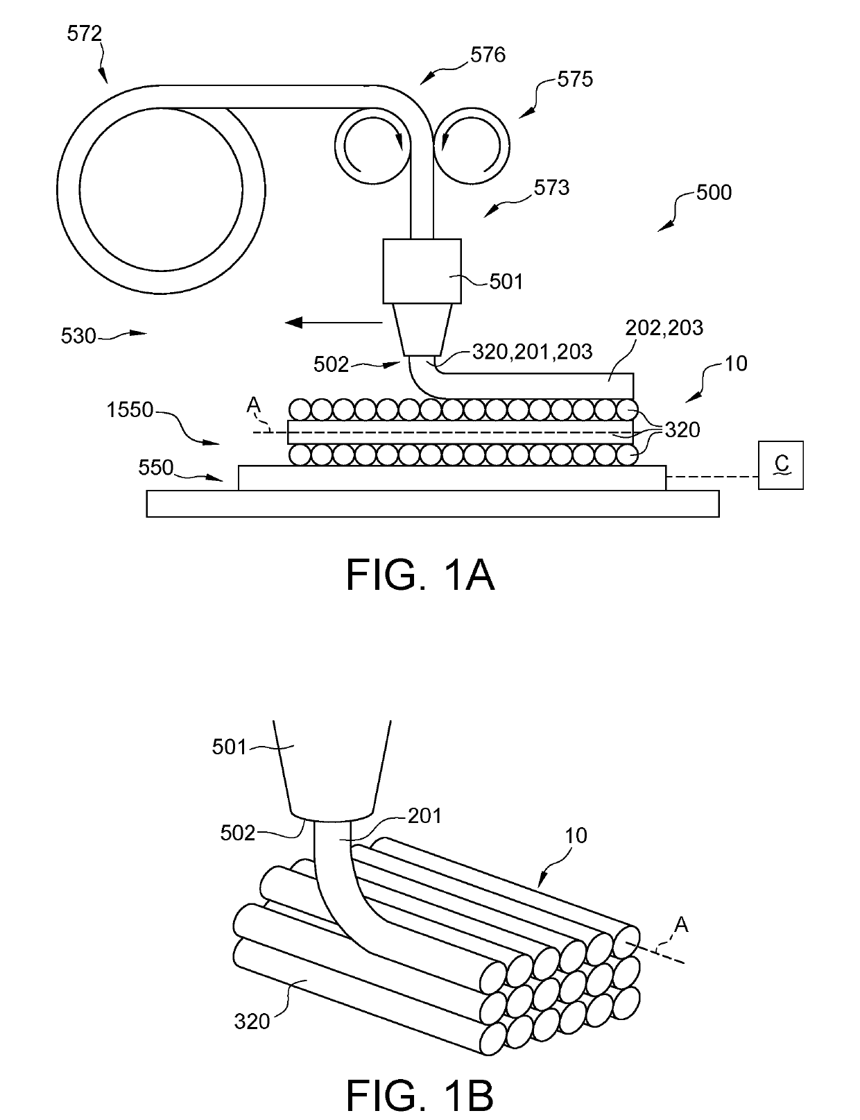
[0062]FIG. 1a schematically depicts some aspects of the 3D printer. Reference 500 indicates a 3D printer. Reference 530 indicates the functional unit configured to 3D print, especially FDM 3D printing; this reference may also indicate the 3D printing stage unit. Here, only the printer head for providing 3D printed material, such as a FDM 3D printer head is schematically depicted. Reference 501 indicates the printer head. The 3D printer of the present invention may especially include a plurality of printer heads, though other embodiments are also possible. Reference 502 indicates a printer nozzle. The 3D printer of the present invention may especially include a plurality of printer nozzles, though other embodiments are also possible. Reference 320 indicates a filament of printable 3D printable material (such as indicated above). For the sake of clarity, not all features of the 3D printer have been depicted, only those that are of especial relevance for the present invention (see furt...


PUM

PropertyMeasurementUnit
core diameteraaaaaaaaaa

Abstract

The invention provides a method comprising 3D printing a 3D item, the method comprising depositing during a printing stage 3D printable material and an optical fiber, to provide the 3D item with the optical fiber at least partly embedded in 3D printed material, wherein the 3D printable material during at least part of the printing stage comprises a light transmissive material, the method further comprising providing during the printing stage a light escape part comprising 3D printed material comprising the light transmissive material, where visible light propagating through the optical fiber can escape from the optical fiber via the 3D printed material comprised by the light escape part to external of the 3D item.

Description

FIELD OF THE INVENTION[0001]The invention relates to a method for manufacturing a 3D (printed) item. The invention also relates to the 3D (printed) item obtainable with such method. Further, the invention relates to a lighting system including such 3D (printed) item. Yet further, the invention also relates to a 3D printer.BACKGROUND OF THE INVENTION[0002]The use of optical fibers in 3D printing technology is known in the art. WO2015 / 077262, for instance, describes 3D printer inputs including filaments comprising separated layers or sections. These inputs particularly including filaments may be prepared by coextrusion, microlayer coextrusion or multicomponent / fractal coextrusion. These inputs, and specifically filaments, are alleged to enable layering or combining different materials simultaneously through one or more nozzles during the so-called 3D printing process. These techniques facilitate smaller layer sizes (milli, micro, and nano) different layer configurations as well as the...

Claims


Application Information

Patent Timeline
Patent Type & Authority Patents(United States)
IPC IPC(8): F21V7/04F21V8/00B33Y30/00B33Y40/00B29C64/30B29C64/118B33Y10/00B33Y80/00B29C64/165B29C64/209B29K309/08B29L11/00
CPCB33Y10/00G02B6/001B33Y80/00B29C64/30B33Y40/00B33Y30/00B29C64/118B29C64/165B29C64/209B29L2011/00G02B6/0003B29K2309/08B29C64/20B33Y40/20
Inventor HIKMET, RIFAT ATA MUSTAFAVAN HAL, PAULUS ALBERTUSVAN BOMMEL, TIES
Owner SIGNIFY HLDG BV
Why Eureka
Try Eureka