Medium distribution assembly and a vehicle design element including such an assembly

a technology of distribution assembly and vehicle design element, which is applied in the direction of vehicle cleaning, lighting and heating apparatus, instruments, etc., can solve the problems of poor optical efficiency, bright or hot spots for external viewers of badges, and poor optical efficiency, so as to avoid negative influence on antennas

Active Publication Date: 2021-03-16
MOTHERSON INNOVATIONS CO LTD
View PDF13 Cites 0 Cited by
  • Summary
  • Abstract
  • Description
  • Claims
  • Application Information

AI Technical Summary

Benefits of technology

[0009]It is proposed that the light guide transitions from the base to the flange or cylinder, sharply with a radius of less than 10% of a height of the flange or cylinder, the sharp transition facilitating internal reflection of light emitted from the light sources.
[0044]In one form, the light guide transitions from the base to the flange sharply with a radius of less than 10% of the height of the flange, the sharp transition facilitating internal reflection of light emitted from the LEDs.
[0050]In one form the circumferential flange is replaced by at least one circumferential cylinder, the transition between the annular base and the circumferential cylinder, facilitating internal reflection of light emitted from the LED's efficiently into the cylinder.
[0052]It is especially preferred that the contamination is automatically detected by a sensing element, especially incorporating a camera. Such a camera allows a detection of the contamination, especially rain and frost on the surface of the design element, which may reduce the radar performance. The use of a camera has furthermore the advantage depending on the location of the design element, especially rear or forward facing at the vehicle, that the camera can also provide a feed of images for other auxiliary functions. Such auxiliary functions might be line tracking, object detection, parking assistance and / or functioning as revising camera especially in case the design element is located on the rear of the vehicle.
[0057]In a second alternative, the sensing element is placed on the backside of the design element and detects contamination by sensing along an angle being parallel to the normal direction of the surface of the design element. To avoid that the sensing element can be recognized from the outside, the sensing element is placed behind a coated section of the design element. A hole or transparent window in the rear overmold allows the sensing element, especially the camera, to view the first surface of the design element to detect contamination. The coating can be semi-transparent, i.e. transparent enough for the sensing element to “look” through and detect contamination. To avoid a negative influence onto the antenna, the sensing element is preferably placed outside the radiation field of the antenna to ensure that the sensing element does not disturb the radar function.

Problems solved by technology

This may result in the appearance of bright or hot spots to an external viewer of the badge.
Highly diffusing materials are also used but these have the drawback of giving a milky or hazy appearance and have poor optical efficiency.
Optic features may also be used on clear materials to diffuse light, but these have the drawback that the optic features are visible in the unlit state which is undesirable.
Contaminations on a surface of such a radome like dust, dirt, snow, ice etc. leads to the problem that the function of the safety critical drive assistance system located at least partly behind the radome, especially of a radar system, cannot be ensured at all times. These impurities can occlude radar sensors, reduce accuracy and the reliability of information provided by the system.
Such a camera allows a detection of the contamination, especially rain and frost on the surface of the design element, which may reduce the radar performance.

Method used


Image

  • Medium distribution assembly and a vehicle design element including such an assembly
  • Medium distribution assembly and a vehicle design element including such an assembly
  • Medium distribution assembly and a vehicle design element including such an assembly

Examples


Embodiment Construction

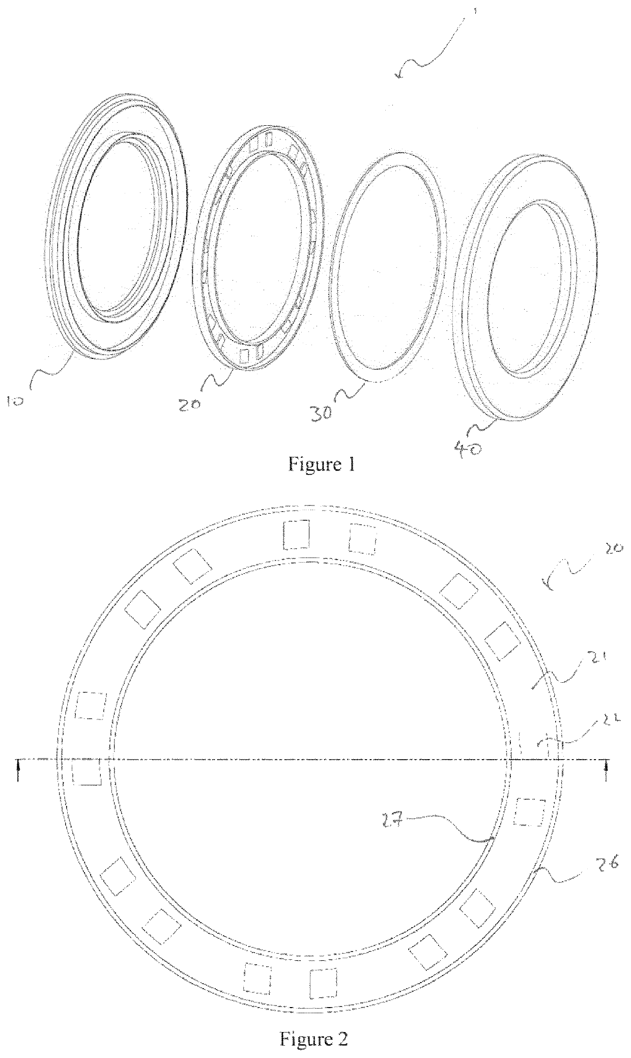
[0089]Referring now to FIG. 1, there is shown an exploded light assembly 1, which has a housing 10, a light guide 20, an annular printed circuit board (PCB) 30 featuring a plurality of light emitting diodes (LEDs, not shown), and a lens 40. The light assembly 1 provides light output such that a viewer would see a homogenous annular light output.

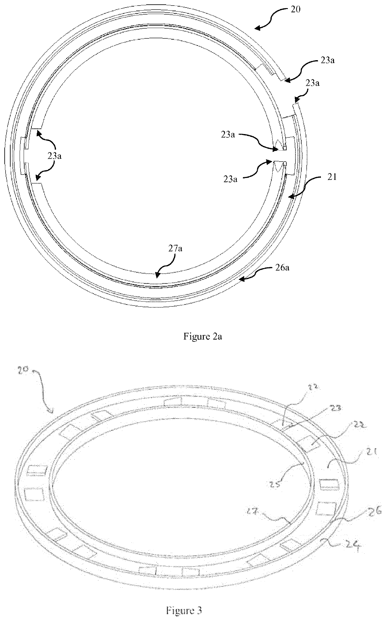
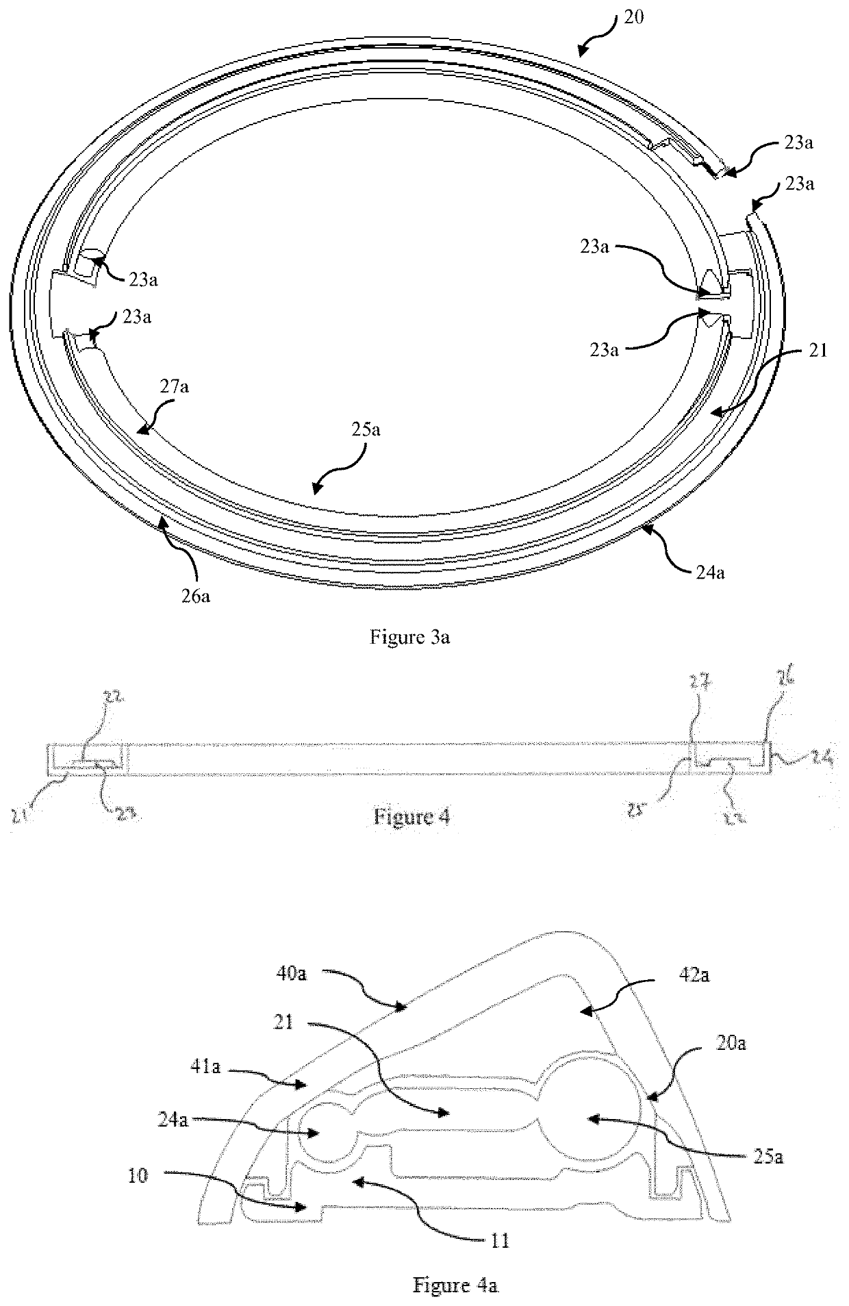
[0090]Referring now to FIGS. 2 and 3 which show a plan and perspective view of the light guide 20, which has an annular base 21, on which there are a plurality of wedge shaped protrusions 22 which feature light receiving surfaces 23. The light guide further comprises an outer circumferential flange 24 and an inner circumferential flange 25, both of which extend away from the annular base 21 towards viewable outer and inner light exits 26 and 27, respectively.

[0091]Referring now to FIGS. 2a and 3a which show a plan and perspective view of the light guide 20, which has an annular base 21. On this annular base could be a plurality of wedge shape...


PUM


Abstract

A medium distributing assembly for a vehicle design element includes a medium guide including at least one medium receiving element; and at least one medium exit element, where the medium exit element has at least partly an annular form.

Description

CROSS-REFERENCE TO RELATED APPLICATION[0001]This application is a continuation-in-part of U.S. patent application Ser. No. 15 / 743,556, which is a national stage entry of International Patent Application No. PCT / EP2016 / 066355, filed Jul. 8, 2016, which claims the benefit of foreign priority to Australian Patent Application No. AU 2015902723, filed Jul. 10, 2015, each of which is incorporated by reference herein in its entirety for all purposes.BACKGROUND1. Field of the Invention[0002]The present disclosure relates to a medium distributing assembly for a vehicle design element, selected from vehicle emblems, badges, logos and the like, which can provide a uniform medium output. In particular the present invention refers to a medium distributing assembly for a vehicle design element, the assembly including: a medium guide the medium guide including at least one medium receiving element and at least one medium exit element, wherein the medium exit element has an at least partly annular ...

Claims


Application Information

Patent Timeline
Patent Type & Authority Patents(United States)
IPC IPC(8): F21S43/241F21S43/14F21S43/40B60R13/00F21V8/00G02B27/00B60Q1/00B60S1/48B60S1/54B60S1/60B60Q1/56G01S7/40H01Q1/32H01Q1/42
CPCB60R13/005B60Q1/00B60Q1/56B60S1/487B60S1/54B60S1/60B60S1/603G01S7/4004G02B6/006G02B6/009G02B6/0045G02B6/0055G02B27/0006H01Q1/3233H01Q1/42G01S2007/4043G02B6/0041B60S1/56H01Q1/3291G02B6/0096B60Q1/0023B60Q1/28B60Q1/30G01S13/86G01S2015/937G01S2013/93271G01S13/931G01S2013/9324G01S2007/52011G01S7/4039G01S7/4043
Inventor CARUSO, DEANHERRMANN, ANDREASTHODAY, SAMGIBSON, BRADFLYNN, DANIELBELCHER, SIMON
Owner MOTHERSON INNOVATIONS CO LTD
Why Eureka
Try Eureka