[0015]A first notable advantage of the invention is increased power efficiency leading to a larger clean area of the protected surface and / or to less power consumption. A second notable advantage of the invention is protection of the protected surface from high intensity radiation close to the light source. It may even be so that the light is blocked from exiting the optical medium at the back surface thereof in the first zone and the third zone, for instance by means of a specularly reflective layer and a scattering layer, respectively, which may be arranged on the optical medium at the back surface thereof, and that the light cannot escape from the optical medium at the back side thereof in the second zone as well, depending on the possible angles at which the light hits the back surface in the second zone, which angles can be kept within certain boundaries on the basis of design particulars of the light emitting arrangement. Furthermore, when the invention is applied, it is possible to have a light emitting arrangement that is transparent in a certain zone outside of the light source, namely at least in the second zone, which allows for visibility of the protected surface.
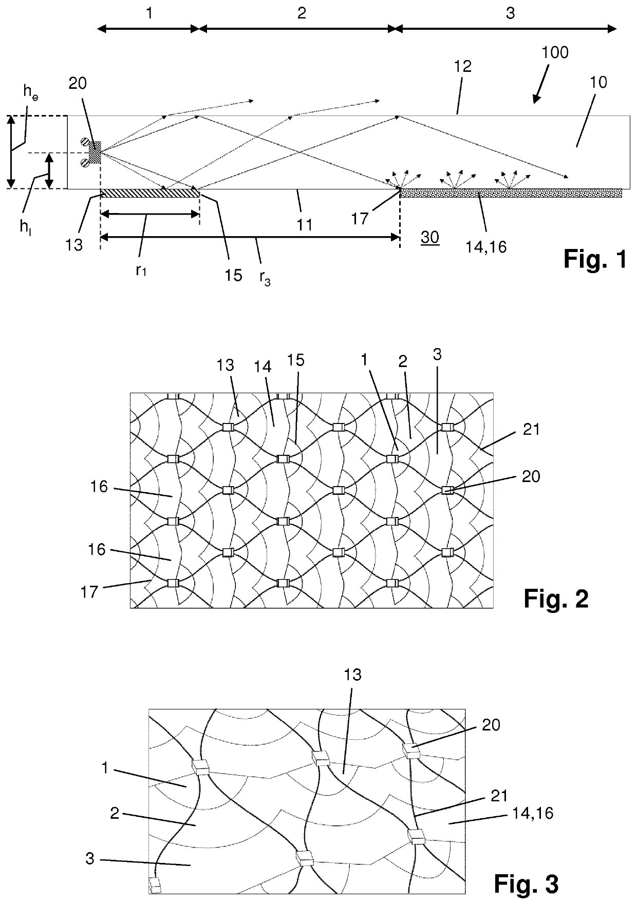
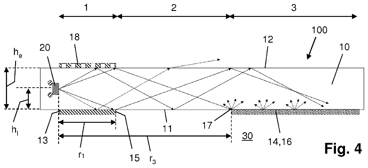
[0016]Advantageously, within the framework of the invention, it may be so that in the first zone, the emission surface of the optical medium is at least partially covered by a mirror, a reflective side of the mirror facing the emission surface. In such a case, the mirror as mentioned serves for decreasing the emission of anti-fouling light at the emission surface of the optical medium in the direct vicinity of the light source, thereby contributing to the desired homogeneous distribution of the light across the emission surface. Preferably, such a mirror is semi-transparent to the anti-fouling light. The mirror may be a patterned mirror, for example. In view of the desired homogeneous distribution of the light across the emission surface, it is an advantageous option to have a design of the semi-transparent mirror in which the extent to which the mirror is semi-transparent to the anti-fouling light increases in a direction away from the light source, so as to allow more light to pass through at a larger distance from the light source.
[0017]In any case, in order to enable the first zone to let the anti-fouling light reflect in a specular manner towards the emission surface of the optical medium, through the optical medium, particularly to let the anti-fouling light reflect at the back surface of the optical medium, it is practical if in the first zone, the back surface of the optical medium is at least partially covered by a mirror, a reflective side of the mirror facing the back surface. Total internal reflection of the light in the second zone may be promoted by providing the back surface of the optical medium with a low-index layer in that zone, which does not alter the fact that it is possible for the back surface of the optical medium to be free from any layer or other means for reducing an index of refraction in that zone. If a low-index layer is applied, it is practical for the index of refraction of that layer to be lower than an index of refraction of the fouling liquid in which the protected surface is to be immersed. Otherwise, adding a layer does not help in promoting total internal reflection when compared to a situation in which only the refractive indices of the material of the optical medium and the fouling liquid are decisive factors. Finally, in order to enable the third zone to let the anti-fouling light scatter out of the optical medium, through the emission surface of the optical medium, particularly to let the anti-fouling light scatter at the back surface of the optical medium, it is practical if in the third zone, the back surface of the optical medium is at least partially covered by a scattering layer, a scattering side of the scattering layer facing the back surface.
[0018]In a preferred embodiment of the light emitting arrangement according to the invention, the light source is positioned closer to a level of the emission surface of the optical medium than to a level of the back surface of the optical medium, so as to have an increased area of the emission surface where the power density of the light is above a predetermined threshold that is known to be relevant when it comes to achieving anti-fouling effects. Furthermore, in order to enhance the effectiveness of the design of the light emitting arrangement according to the invention, the light source may be arranged and configured so as to emit more than 50% of the anti-fouling light directly towards the back surface of the optical medium in the first zone. In this way, it can be achieved that in the first zone, a major part of the light is made to reflect in a specular manner and allowed to reach the second zone rather than to be emitted directly from the optical medium at the emission surface.
[0019]According to an insight underlying the invention, it is advantageous for the first zone to have a substantially circularly curved outer boundary and for the third zone to have a substantially circularly curved inner boundary, the light source being at the center of the circular shapes, so that the boundaries are at a constant distance from the light source as seen along the directions in which the anti-fouling light may travel from the light source. In order to achieve that in the first zone at least a major part of the light is reflected in a specular manner towards the emission surface of the optical medium, that in the second zone at least a major part of the light is propagated through the optical medium by total internal reflection, and that in the third zone at least a major part of the light is scattered out of the optical medium, through the emission surface of the optical medium, it is advantageous to relate a radial distance between the outer boundary of the first zone and the light source to positional aspects of the light source in the optical medium and a critical angle for total internal reflection in the optical medium and / or to relate a radial distance between the inner boundary of the third zone and the light source to dimensional aspects in the optical medium, positional aspects of the light source in the optical medium and a critical angle for total internal reflection in the optical medium. In particular, a radial distance between the substantially circularly curved outer boundary of the first zone and the light source may be chosen so as to be equal to or larger than hl / tan(90°−0), and / or a radial distance between the substantially circularly curved inner boundary of the third zone and the light source may be chosen so as to be equal to or larger than (he+(he−hl)) / tan(90°−θ), in which hl represents a height level of the light source with respect to the back surface of the optical medium, in which he represents a height level of the emission surface of the optical medium with respect to the back surface of the optical medium, and in which θ represents a critical angle for total internal reflection in the optical medium, which is defined as arcsin(n2 / n1), in which n1 represents an index of refraction of the material of the optical medium, and in which n2 represents an index of refraction of the fouling liquid in which the protected surface is to be immersed. In that way, it can be achieved that the design of the light emitting arrangement is optimized by taking the behavior of the anti-fouling light in the environment constituted by the optical medium and the adjacent fouling liquid into account, particularly the behavior as based on a range of angles of impact on the emission surface in which the light is capable of escaping from the optical medium and a range of angles of impact on the emission surface associated with total internal reflection of the light in the optical medium.
[0020]In a practical embodiment of the light emitting arrangement according to the invention, the optical medium is in the form of a slab, wherein the emission surface of the optical medium and the back surface of the optical medium are substantially planar and extend substantially parallel to each other. In that embodiment, the optical medium is very well suitable to be applied as a cover to the protected surface.

