Strip lighting device

a lighting device and strip technology, applied in the direction of lighting and heating equipment, instruments, fibre light guides, etc., can solve the problems of limiting the control of light output along the length unable to modify the appearance of the light pipe, and difficult to achieve an even intensity of illumination along the pointer

Inactive Publication Date: 2016-05-12
VISTEON GLOBAL TECH INC
View PDF4 Cites 1 Cited by
  • Summary
  • Abstract
  • Description
  • Claims
  • Application Information

AI Technical Summary

Benefits of technology

The patent describes a device that uses a light pipe to spread and scatter light from a light source. The depth of angled portions in the light pipe can be adjusted to control the amount of light and make it even across the device. By the end closest to the light source, the angled portions are deeper and the length of the regions between them is shorter, resulting in more light exiting the pipe and spreading through the device. This technology can be used to create displays and other lighting devices with better control over the light output.

Problems solved by technology

While the use of these known extracting features can be an effective and simple mechanism for creating the desired illumination in some circumstances, there are situations in which it is not possible or desirable to include the extraction features, thereby limiting the control of light output along the length of the light pipe.
As such, it is not possible to modify the appearance of the light pipe through the introduction of extracting features, for example surface texturing, to enable the amount of light extracted from the light pipe to be controlled.
It can be difficult to achieve an even intensity of illumination along the pointer and, typically, the illumination varies significantly between the root and the tip of the pointer arm.
The use of current methods and extraction features, however, typically cannot achieve an illumination intensity variation along a pointer arm of less than 10%, without noticeably affecting the appearance of the pointer arm.

Method used


Image

  • Strip lighting device
  • Strip lighting device
  • Strip lighting device

Examples


first embodiment

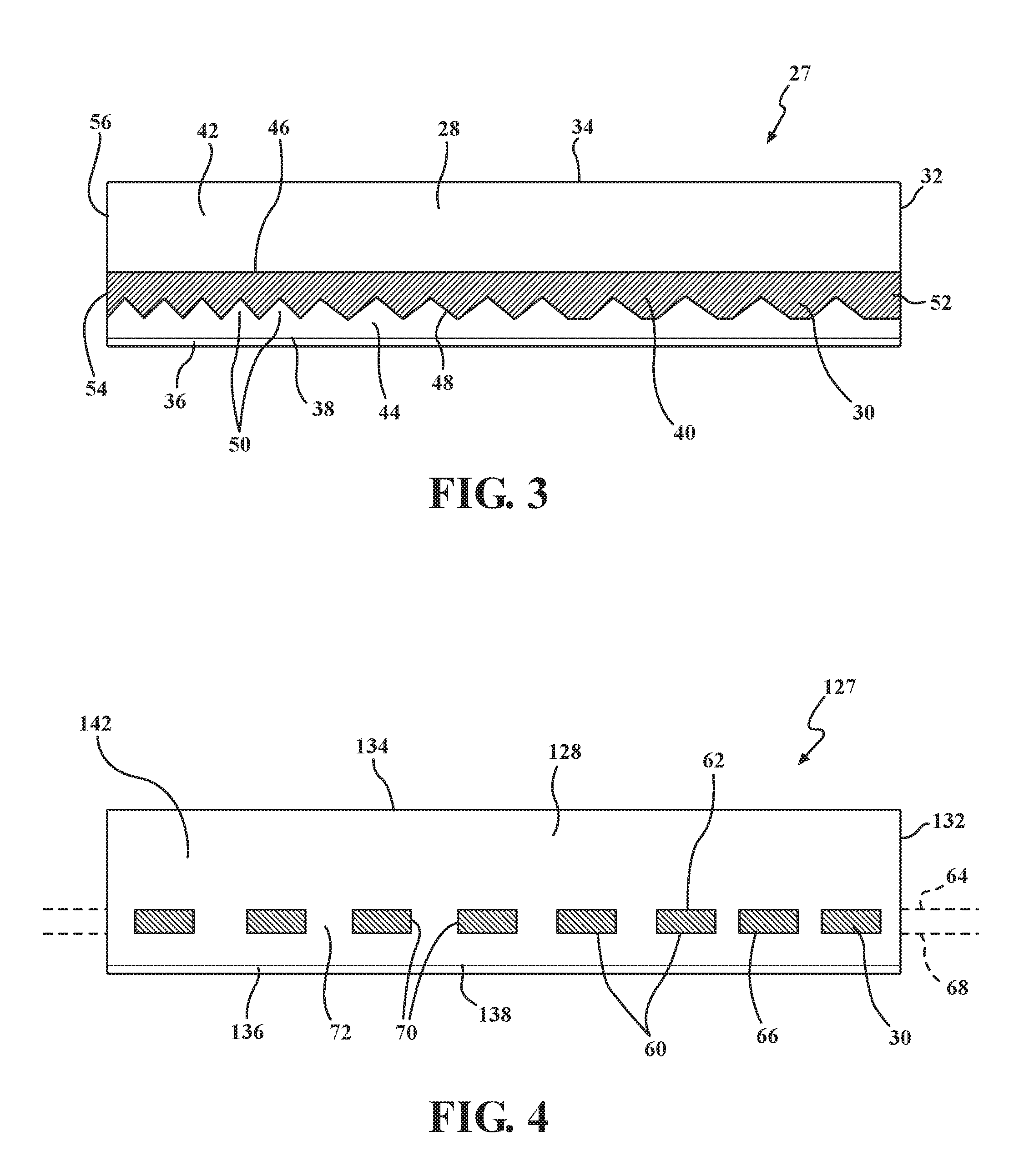
[0041]a dual material light guide 27 for use in a pointer arm 14 is shown in FIG. 3. For simplicity, the light guide 27 has a substantially rectangular cross-sectional shape such that the front face 34 of the light guide 27 is parallel to the rear face 38 of the light guide 27. The rear face 38 of the light guide 27 is covered by a layer of scattering foil 36, which forms a light scattering coating 36 as is known in the art, that acts to scatter light incident on the rear face 38, as described further below.

[0042]The body 28 of the light guide 27 is made of a first light transmissive material which has a lower refractive index than a second light transmissive material that forms a central layer or core 40 of the light guide 27. In this example, the first light transmissive material is polymethyl methacrylate (PMMA) having a refractive index of about 1.49, and the second light transmissive material is polycarbonate (PC) having a refractive index of about 1.58.

[0043]In this example, t...

second embodiment

[0058]a dual material light guide 127 for use in a pointer arm 14 is shown in FIG. 4. Many of the features of this light guide 127 are the same as features of the previous embodiment and like features have been indicated by reference numerals incremented by 100.

[0059]As before, the light guide 127 has a substantially rectangular cross-sectional shape such that a front face 134 of the light guide 127 is parallel to a rear face 138 of the light guide 127. The rear face 138 of the light guide 127 is textured and metalized, as is known in the art, to provide a light scattering portion 136 to reflect and scatter light that is incident on the rear face 138.

[0060]The body 128 of the light guide 127 is made of a first light transmissive material having a higher refractive index than a second light transmissive material which forms discrete regions or islands 60 within the body 128 of the light guide 127. In this example, the first light transmissive material is polycarbonate (PC) having a r...


PUM


Abstract

A strip lighting device includes a main body having front and rear sides extending along a length of the main body. The front side is disposed towards a viewer of the device and the rear side includes a light scattering layer for scattering light from a source of illumination towards the viewer when the device is illuminated. The main body has a front and rear cladding layer each of which is made of a first light transmissive material. The strip lighting device includes a light pipe made of a second light transmissive material sandwiched between the front and rear cladding layers at interfaces extending along the length of the main body. A rear interface of the light pipe has a plurality of angled portions which allow some light to escape into the rear cladding layer to impinge on the light scattering layer and scatter light towards the viewer.

Description

CROSS REFERENCE TO RELATED APPLICATIONS[0001]This U.S. Divisional patent application claims priority to U.S. patent application Ser. No. 14 / 184,326 filed Feb. 19, 2014 which claims the benefit of United Kingdom Patent Application No. 1303410.3 filed Feb. 26, 2013, entitled “Strip Lighting Device,” the entire disclosures of the applications being considered part of the disclosure of this application and hereby incorporated by reference.BACKGROUND[0002]a. Field of the Invention[0003]This invention relates to a strip lighting device and to a pointer for a display including such a strip lighting device. More particularly this invention relates to a strip lighting device for use in a pointer of a motor vehicle display.[0004]b. Related Art[0005]Light pipes or light guides are known for use in the illumination of moving pointers in displays and also for the static illumination of display surfaces or other features. These light pipes find particular use in motor vehicle dashboard displays. ...

Claims


Application Information

Patent Timeline
Patent Type & Authority Applications(United States)
IPC IPC(8): G01D13/26F21V8/00
CPCG02B6/001G01D13/265G02B6/0018G01D11/28B60K2360/6992B60Q3/62F21V13/04G02B6/0005
Inventor GULLICK, DANIELMURZYN, PAWEL
Owner VISTEON GLOBAL TECH INC
Why Eureka
Try Eureka