
Attached resistance strain sensor assembly and mounting process thereof

Active Publication Date: 2020-11-19
HU TIANXU
View PDF0 Cites 1 Cited by
  • Summary
  • Abstract
  • Description
  • Claims
  • Application Information

AI Technical Summary

Benefits of technology

The invention is a small-size sensor that can measure large loads and has improved mounting efficiency and working reliability. It can be used for monitoring parameters such as overload and underload limitation of a load, structural deflection, deformation and the like. The sensor assembly is attached to a measuring point on the surface of the structure via a substrate and bears extremely small component force, the dynamic work is very safe, and a large load can be measured by a small-size sensor. The sensor assembly is simplified in installation, improves matching among all parts, and prolongs the reliability and service life of the sensor assembly. The assembling of the sensor assembly is carried out in a manufacturing factory instead of a use field, ensures the matching requirements of all parts and the mounting quality of the assembly such as sealing, moisture resistance, heat insulation and the like, and improves the reliability and service life of the sensor assembly.

Problems solved by technology

The on-site installation of the sensor is time-consuming, laborious and troublesome.
The mounting has a long time and must take place while the equipment is down, often affecting production.
In addition, due to the limitation of field conditions, it will influence the mounting quality and then the working reliability of the sensor.
The sensor based on the elastomer with the existing structural size cannot meet the requirements of large variation range of deformation values of a structure measuring point of field equipment and mounting size of the measuring point.

Method used


Image

  • Attached resistance strain sensor assembly and mounting process thereof
  • Attached resistance strain sensor assembly and mounting process thereof
  • Attached resistance strain sensor assembly and mounting process thereof

Examples


example 1

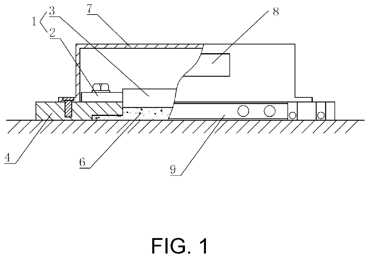
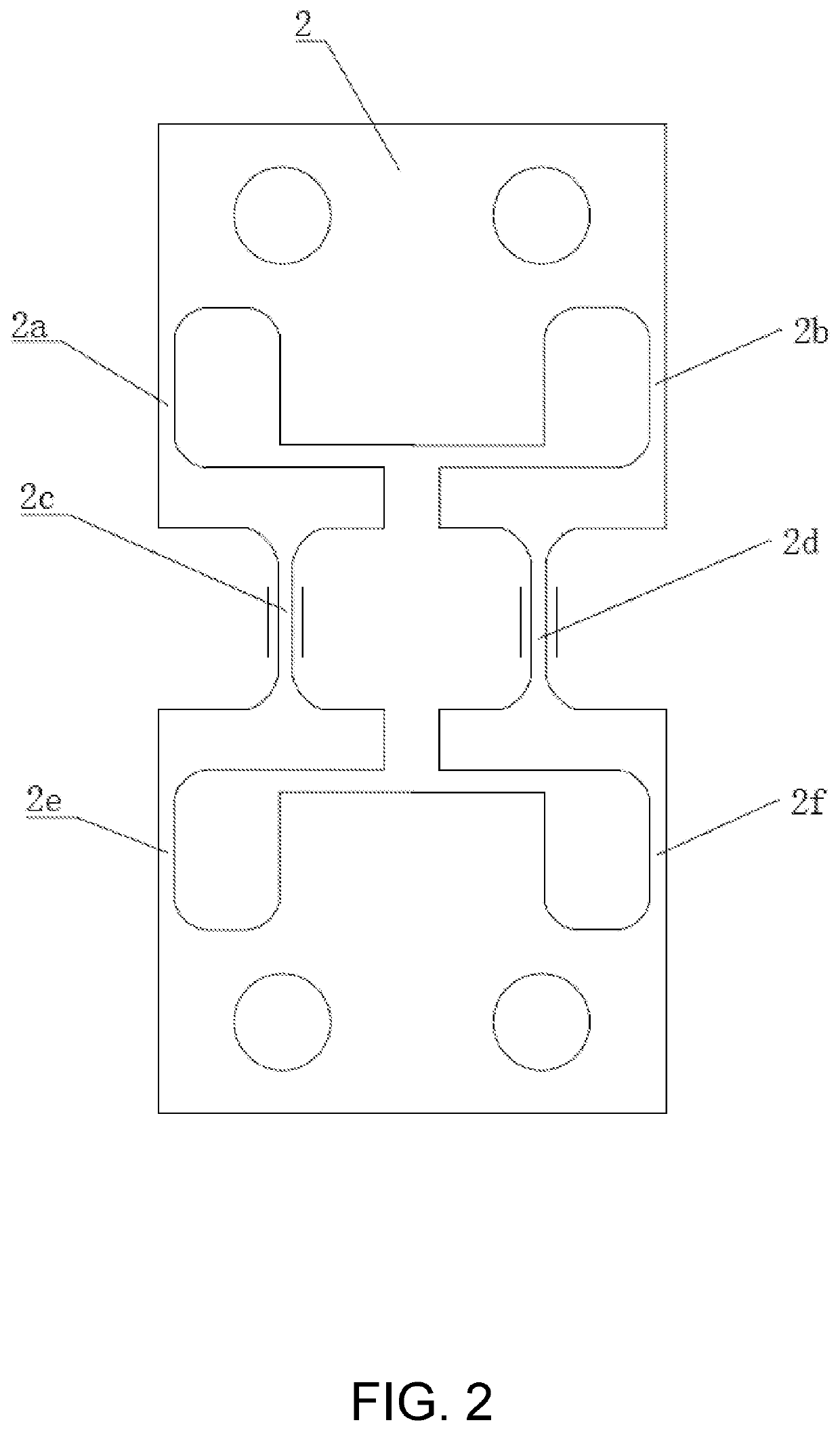
[0040]As shown in FIGS. 1 and 2, an attached resistance strain sensor assembly comprises a sensor body 1. The sensor body 1 comprises an elastomer 2 and a full-bridge type measuring bridge 3. Six elastic bridges are provided on the elastomer 2, the elastomer 2 is divided into an upper section, a middle section and a lower section along a central axis, the structure of each of the sections is a bilaterally symmetrical distribution, and the shapes of the left part and the right part of the middle section are I-shaped respectively; the left edge of the upper section is provided with a first elastic bridge 2a connected with a starting position of a first stroke of an I-shaped character at the left part of the middle section, the right part of the upper section is provided with a second elastic bridge 2b which is symmetrical to the first elastic bridge 2a, a second stroke of the I-shaped character at the left part of the middle section is provided as a third elastic bridge 2c, the right ...

example 2

[0050]Example 2 differs from Example 1 in that the elastomer 2 is different as shown in FIG. 4. Six elastic bridges are provided on the elastomer 2, the elastomer is divided into an upper section, a middle section and a lower section along a central axis, the structure of each of the sections is a bilaterally symmetrical distribution, and the shapes of the left part and the right part of the middle section are I-shaped respectively; the left part of the upper section is provided with a first elastic bridge 2a connected with a ending position of a first stroke of an I-shaped character at the left part of the middle section along the central axis, the right part of the upper section is provided with a second elastic bridge 2b which is bilaterally symmetrical to the first elastic bridge 2a, a second stroke of the I-shaped character at the left part of the middle section is provided as a third elastic bridge 2c, the right part of the middle section is provided with a fourth elastic brid...

example 3

[0051]An attached resistance strain sensor is used for a 35t bridge crane of Shagang to carry out overload limitation and real-time process metering. With a FWZ-C-35t type instrument, sensors are installed in the middle of the upper surfaces of slot holes of the supporting plate at the two ends of the fixed pulley shaft. ψ=23, L0=50 mm, Qm=36.1t, δm=2×27.5 mV / 10V.


PUM


Abstract

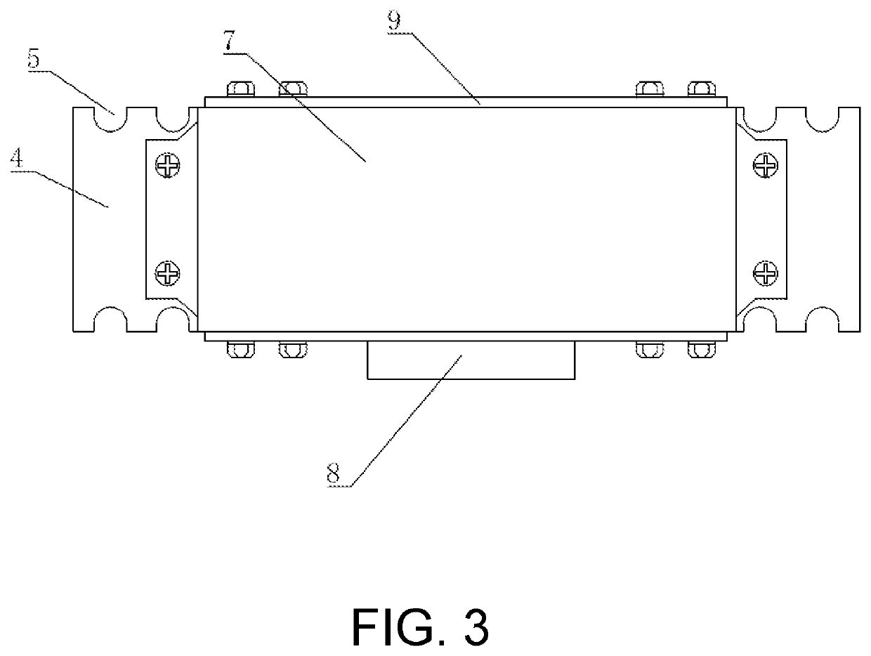
The invention discloses an attached resistance strain sensor assembly includes a sensor body, wherein substrates are respectively mounted at two ends of a lower end face of the sensor body, a heat insulation layer is provided between two of the substrates, the heat insulation layer covers the lower end face of the sensor body, an outer cover is covered above the sensor body, two ends of the outer cover are respectively mounted on the two substrates, and a wiring terminal is provided at one side of the outer cover. The sensor assembly can be mounted to a structural member by electric welding, so that the influence of high temperature on the performance of an elastic part in the sensor body during welding is reduced, the output value of the sensor is still in an expected range, and a more accurate load measurement value can be obtained.

Description

CROSS-REFERENCE TO RELATED APPLICATION[0001]This application claims the priority benefit of China application serial no. 201910403186.8, filed on May 15, 2019. The entirety of the above-mentioned patent application is hereby incorporated by reference herein and made a part of this specification.BACKGROUNDTechnical Field[0002]The invention relates to a sensor, in particular to an attached resistance strain sensor assembly and a mounting process thereof.Description of Related Art[0003]Generally, the resistance strain sensor is classified and serialized according to the load value and can only be used for load measurement. When working, the sensor must be connected in series to the load chain to withstand a full load measured. Therefore, when the sensor is selected, the sensor with a large load is often required to be selected. Large load sensors tend to be larger in size. The on-site installation of the sensor is time-consuming, laborious and troublesome.[0004]In order to solve the pr...

Claims


Application Information

Patent Timeline
IPC IPC(8): G01L1/22
CPCG01L1/2287G01L1/2262G01B7/18
Inventor HU, TIANXU
Owner HU TIANXU
Learn More